Level time 0 – VEGA VEGAFLEX 82 Foundation Fieldbus User Manual
Page 61
61
9 Diagnostics and service
VEGAFLEX 82 • Foundation Fieldbus
44221-EN-130910
1
2
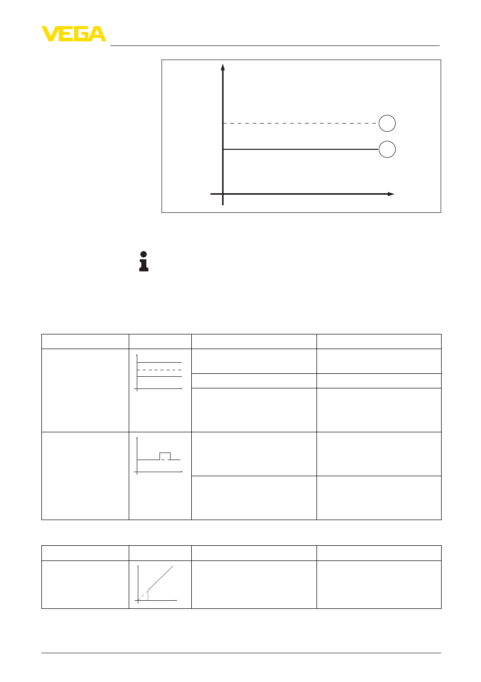
Level
time
0
Fig. 41: The broken line 1 shows the real level, the continuous line 2 shows the
level displayed by the sensor
Note:
•
Wherever the sensor displays a constant value, the reason could
also be the fault setting of the current output to "Hold value"
•
In case of a too low level indication, the reason could be a line
resistance that is too high
Measurement error with constant level
Fault description
Error pattern
Cause
Rectification
1. Measured value
shows a too low or too
high level
Leve
l
time
0
– Min./max. adjustment not
correct
– Adapt min./max. adjustment
– Wrong linearization curve
– Adapt linearization curve
– Running time error (small
measurement error close to
100 %/serious error close to
0 %)
– Repeat setup
2. Measured value
jumps towards 100 %
Level
time
0
– Due to the process, the ampli-
tude of the product echo sinks
– A false signal suppression was
not carried out
– Carry out a false signal sup-
pression
– Amplitude or position of a
false signal has changed (e.g.
buildup); false signal suppres-
sion no longer matches
– Determine the reason for the
changed false signals, carry out
false signal suppression, e.g.
with buildup
Measurement error during filling
Fault description
Error pattern
Cause
Rectification
3. Measured value re-
mains in the area of the
bottom during filling
Leve
l
time
0
– Echo from the probe end larger
than the product echo, for
example, with products with
ε
r
< 2.5 oil-based, solvents, etc.
– Check parameter "Medium"
and "Vessel height", adapt if
necessary