4 mounting instructions – VEGA VEGAPULS 68 (≥ 2.0.0 - ≤ 3.8) Foundation Fieldbus User Manual
Page 16
7
Check, if the O-ring seal is available on the connection piece and if
it is not damaged.
Note:
A damaged O-ring seal must be replaced: FKM (Viton) article no.
2.28248, FFKM (Kalrez 6375) article no. 2.27351
8
Remount the parabolic antenna (4)
9
Tighten compression nut (1) with SW 41, torque max. 50 Nm
10 Tighten locknut (2) with SW 36, torque max. 40 Nm.
Note:
Take note for VEGAPULS 68 with rinsing air connection that the holes
in the antenna and in the process fitting correspond. This ensures a
sufficient air flow (the air is led through the holes to the feed system. A
rinsing of the parabolic antenna in total is not intended).
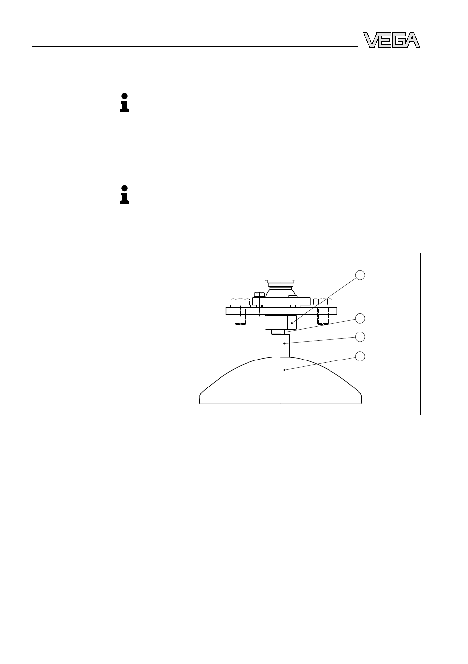
1
2
3
4
Fig. 6: Dismounting, parabolic antenna
1
Compression nut
2
Locknut
3
Connection piece
4
Parabolic antenna
4.4 Mounting instructions
The illustrations with the following mounting instructions show a
VEGAPULS
68 with horn antenna. The mounting instructions apply
analogously also to the version with parabolic antenna.
Mount the sensor at least 200 mm (7.874 in) away from the vessel
wall.
Horn and parabolic an-
tenna
Mounting position
16
VEGAPULS
68 • Foundation Fieldbus
4 Mounting
29264
-EN
-090305