VEGA VEGAMET 624 User Manual
Page 21
21
6 Setup with the integrated display and adjustment unit
VEGAMET 624 • 4 … 20 mA/HART
28969-EN-130701
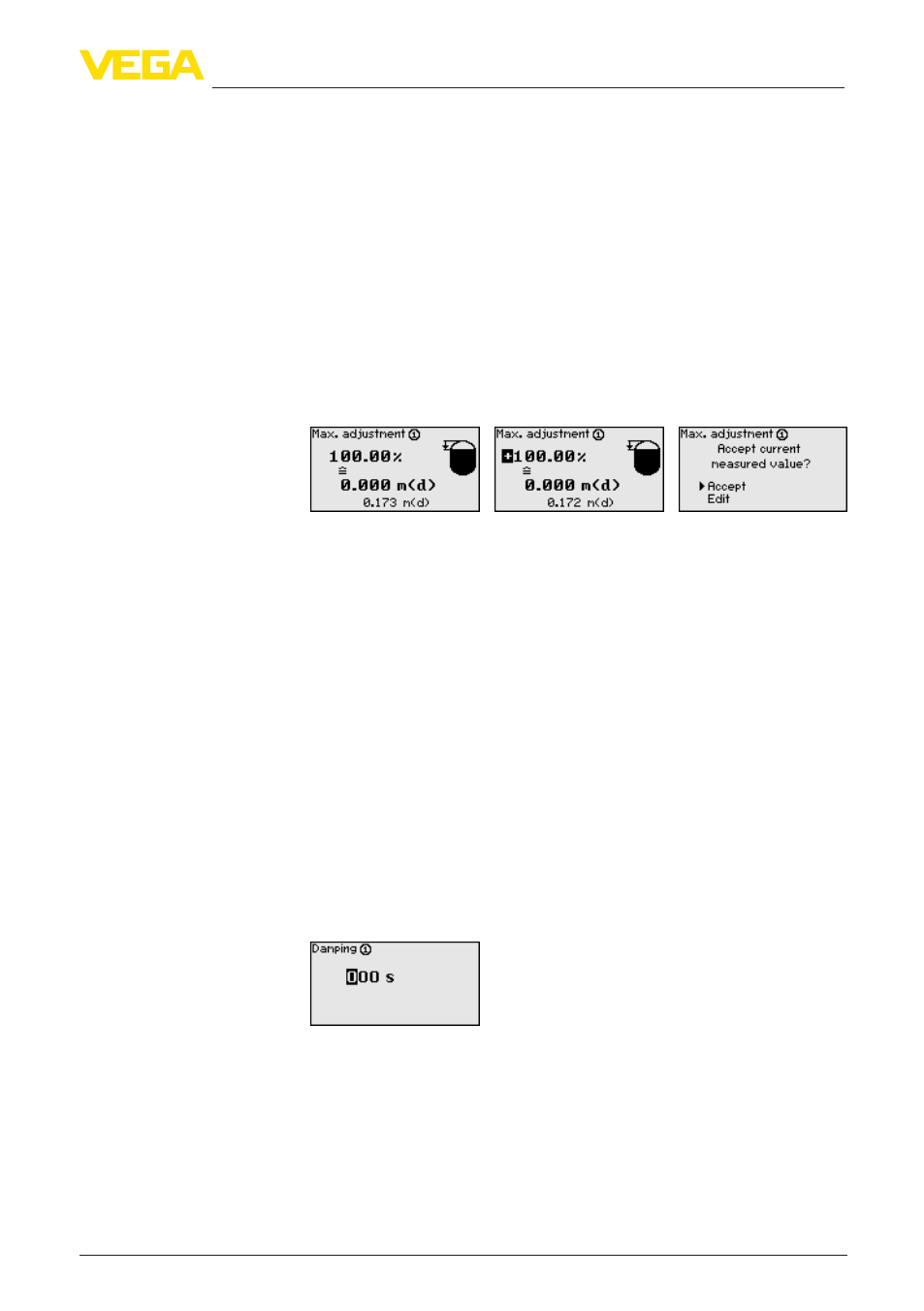
1. With
[OK] you prepare the percentage value for editing, with [->]
you place the cursor to the requested position. Set the requested
percentage value with [+] and save with [OK].
2. After entering the percentage value for the min. adjustment, the
suitable distance value must be entered. If you want the use the
currently measured distance value, select the menu item "Accept"
(live adjustment or adjustment with medium). If the adjustment
should be carried out independent of the measured level, then
select the option "Edit". Enter now the distance value in m [m(d)]
for the empty vessel that is suitable for the percentage value, e.g.
distance from the sensor to the vessel bottom (dry adjustment or
adjustment without medium).
3. Save your settings with [OK] and move to "Max. adjustment" with
[->].
4. As described previously, enter now the percentage value for max.
adjustment and confirm with [OK].
5. After entering the percentage value for the max. adjustment, the
suitable distance value must be entered. If you want the use the
currently measured distance value, select the menu item "Accept"
(live adjustment or adjustment with medium). If the adjustment
should be carried out independent of the measured level, then
select the option "Edit". Enter now the distance value in m [m(d)]
for the full vessel that is suitable for the percentage value (dry
adjustment or adjustment without medium). Keep in mind that the
max. level must be below the radar antenna.
6. Finally save your settings with [OK], the adjustment is finished.
To suppress fluctuations in the measured value display, e.g. caused
by an agitated product surface, an integration time can be set. This
time can be between 0 and 999 seconds. Remember that the reaction
time of the entire measurement will then be longer and the sensor will
react to measured value changes with a delay. In general, a period of
a few seconds is sufficient to smooth the measured value display.
→
Enter the requested parameters via the appropriate keys and
save your settings with [OK].
A linearization is necessary for all vessels in which the vessel volume
does not increase linearly with the level, for example, with a cylindrical
or spherical tank. Corresponding linearization curves are prepro-
grammed for these vessels. They represent the correlation between
the level percentage and vessel volume. By activating the appropriate
curve, the volume percentage of the vessel is displayed correctly. If
Meas. loop - Damping
Meas. loop - Linearization
curve