2 setup sequence, 3 adjustment – VEGA VEGAMET 602 User Manual
Page 15
VEGAMET 601, 602
15
Setup
Potentiometer
With the potentiometers (1 and 2) you can
carry out the max. and min. adjustment.
Control lamps
Green (3)
- supply voltage available
- ready for operation
Red (9)
- failure indication
Analogue display (6)
Indication of the actual level relating to the
adjustment 0 % … 100 %. Resolution in 11
segments.
DIL switch (11)
On top, to the side - covered by the plug-in
socket when the signal conditioning instru-
ment is mounted.
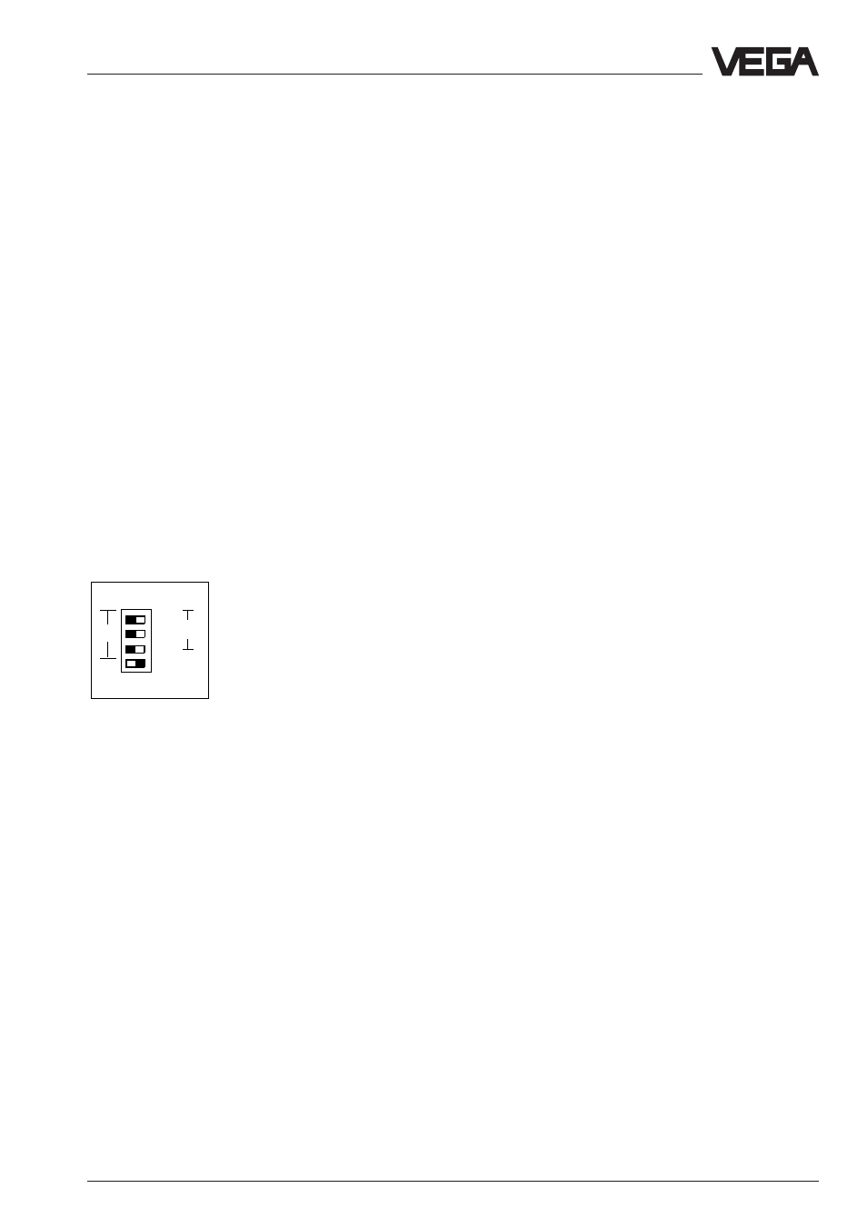
Description of the DIL switch positions
off
4..
12
6
2
0..20mA
t sec
With the upper three DIL switches you can
set an integration time. If all three are set to
position "off", the integration time is zero sec-
onds. With switch "2" two seconds are set,
with switch "6" six seconds are set, etc. If
several switches are set to "on", the time
intervals will be summed up. It is therefore
possible to set 2, 6, 8,12, 18 or 20 seconds
as integration time.
With the fourth DIL switch you choose if you
want to have a 4 … 20 mA or a 0 … 20 mA
current output.
4.2 Setup sequence
The following list gives you a short descrip-
tion of the setup steps
- mount the plug-in socket
- wire the plug-in socket acc. to your control
requirements
- cover the input terminals with the separat-
ing wall (4)
- set the range of the current output on the
DIL switch (11)
- set the integration time on the DIL switch
(11) to "off"
- now mount the module unit into the plug-in
socket
- switch on the power supply, the green LED
(3) lights
- carry out the adjustment acc. to "Section
4.3"
- if an integration time is necessary, the in-
strument must be removed again and the
respective setting must be made on the
DIL switch.
4.3 Adjustment
The adjustment of the empty and full levels is
made via two spindle potentiometers. For the
adjustment procedure, it is useful to connect
a voltmeter to the voltage output 0 … 10 V.
This means:
- empty adjustment, vessel empty corre-
sponds to 0.0 Volt or level 0 %
- full adjustment, vessel full corresponds to
10.0 Volt or level 100 %
Note the following adjustment examples. As a
rule, the potentiometer 1 must first be turned
approx. 22 revolutions clockwise before the
empty and full adjustment is carried out.
As an additional aid to adjustment, the lowest
segment of the analogue display flashes at
0.0 V and the highest at 10.0 V.