Electrical connection – VEGA VEGAPULS 54K enamel User Manual
Page 26
26
VEGAPULS 54K enamel
24 101-EN-041227
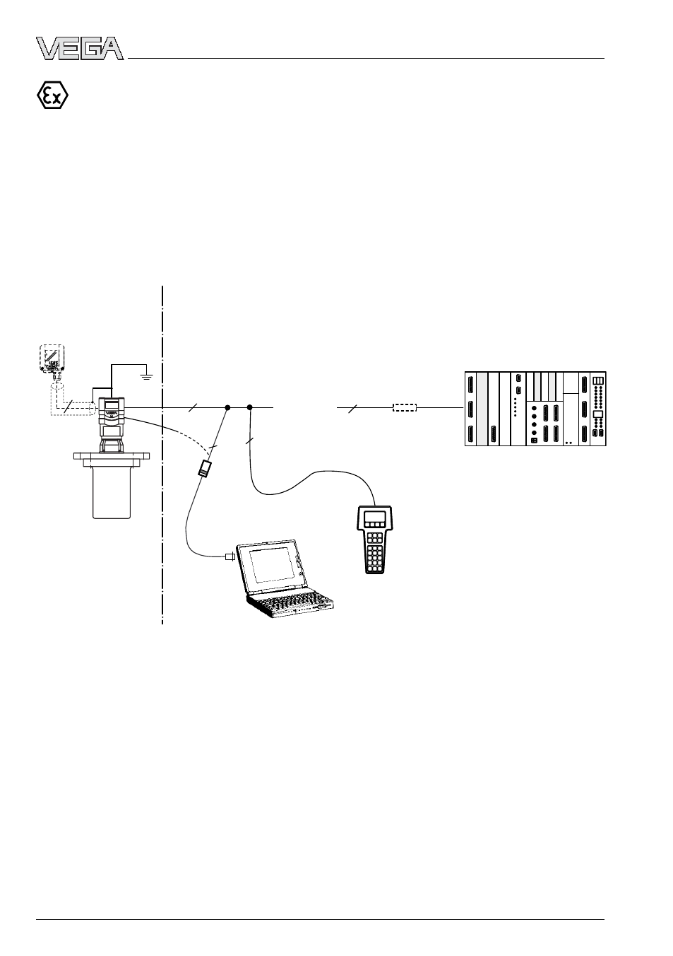
Electrical connection
VEGAPULS 54K Ex (loop powered) with pressure-tight encapsulated
connection compartment on active PLC
• Two-wire technology, supply via the cable from active PLC to Exd connection housing for
operation in Ex-Zone 1 (VEGAPULS …K Ex) or Ex-Zone 0 (VEGAPULS …K Ex0).
• Output signal 4 … 20 mA (passive).
• Measured value display integrated in the sensor.
• Optional external indicating instrument with analogue and digital display (can be mounted
up to 25 m away from the sensor in Ex area).
• Adjustment with PC, HART
®
handheld or adjustment module MINICOM (can be plugged into
the sensor or into the external indicating instrument VEGADIS 50).
1)
If the resistance of the processing systems
connected to the 4 … 20 mA signal output is less
than 200
Ω, a resistor must be connected to the
connection cable during adjustment to get a loop
resistance between 250
Ω up to 300 Ω.
The digital adjustment signal would otherwise be
severely damped or short-circuited due to
insufficient resistance of the connected process-
ing system. Digital communication with the PC or
the HART
®
handheld would not be ensured.
4 … 20 mA
2
2
2
2
4
1)
EEx d ia
EEx e
VEGA-
CONNECT 2
VEGADIS 50 Ex
passive
2)
Ex area
Non Ex area
HART
®
handheld
PLC (active)
2)
4 … 20 mA passive means that the sensor
consumes a level-dependent current of
4 … 20 mA. The sensor reacts electrically like a
varying resistor (consumer) to the PLC.