4 configuration of measuring systems – VEGA VEGAPULS 54K enamel User Manual
Page 20
20
VEGAPULS 54K enamel
24 101-EN-041227
2
4 … 20 mA
-
+
1)
4
> 250
Ω
A measuring system consists of a sensor
with 4 … 20 mA signal output and a unit that
evaluates and further processes the level-
proportional current signal.
On the following pages, you will see a
number of instrument configurations, desig-
nated as "measuring systems“, some of
which are shown with signal processing
units.
Measuring systems in two-wire technol-
ogy:
• 4 … 20 mA shown without processing unit
• 4 … 20 mA on active PLC
• 4 … 20 mA on active PLC (Ex area),
• 4 … 20 mA on passive PLC
• 4 … 20 mA on indicating instrument
VEGADIS 371 Ex
Measuring systems in four-wire technol-
ogy:
• 4 … 20 mA shown without signal condition-
ing instrument
VEGADIS 50
VEGA-
CONNECT 2
HART
®
handheld
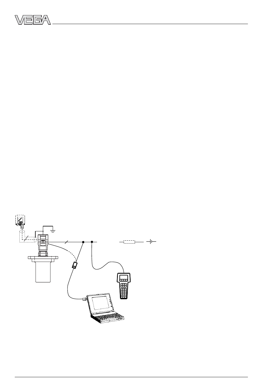
Electrical connection
Measuring systems with VEGAPULS 54K on any voltage source
• Two-wire technology (loop powered), supply and output signal via one two-wire cable.
• Output signal 4 … 20 mA (passive).
• Optional external indicating instrument with analogue and digital display (can be mounted
up to 25 m away from the sensor).
• Adjustment with PC, HART
®
handheld or the adjustment module MINICOM (can be plugged
into the sensor or into the external indicating instrument VEGADIS 50).
1)
If the resistance of the processing systems
connected to the 4 … 20 mA signal output is less
than 200
Ω, a resistor must be connected to the
connection cable during adjustment to get a loop
resistance of 250
Ω up to 350 Ω.
The digital adjustment signal would otherwise be
severely damped or short-circuited due to
insufficient resistance of the connected process-
ing system. Digital communication with the PC
would not be ensured.
3.4 Configuration of measuring systems