2 connection plics® sensor – VEGA Remote parameter adjustment and remote maintenance User Manual
Page 3
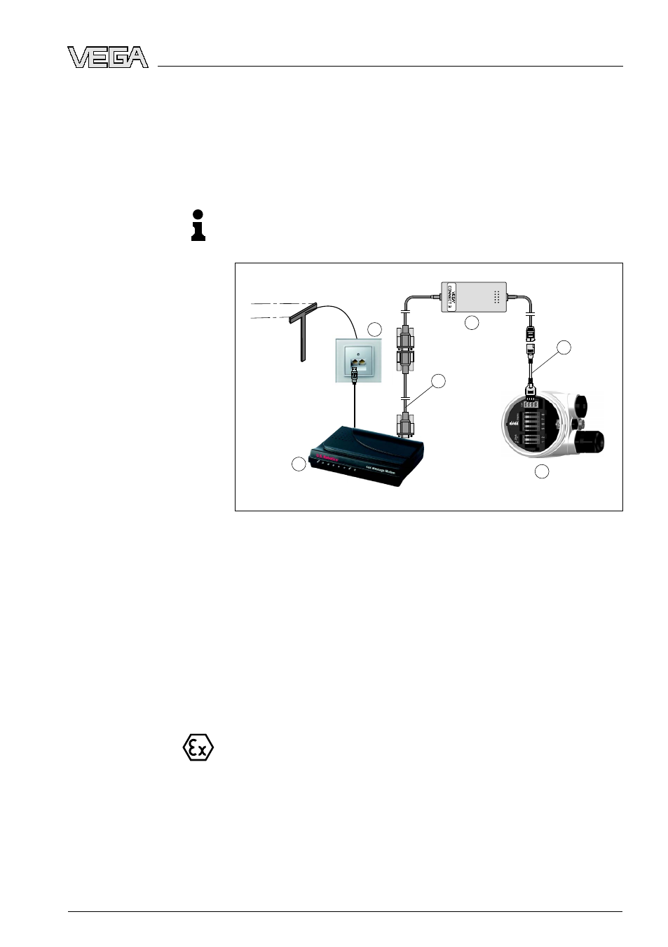
2 Connection plics® sensor
With this version, connection of VEGACONNECT 3 is carried out via
the I²C interface integrated in the sensor. This is the easiest and
fastest way to make a connection. The housing cover of the sensor
cannot be closed when VEGACONNECT 3 is connected.
Note:
Use this connection variant only if the connection is to be short-term, in
a dry environment and not in an Ex-area.
5
6
2
3
1
4
Fig. 2: Connection plics
®
series via I²C interface
1
Analogue telephone connection (not applicable in case of GSM radio
modem)
2
Standard analogue modem or GSM radio modem
3
Special cable, art. no.: MODEM.KX
4
VEGACONNECT 3
5
I²C adapter (in the scope of delivery of VEGACONNECT 3)
6
Sensor from the plics® serie
With this version, connection of VEGACONNECT 3 is carried out via
the HART protocol and the supply cable of the sensor. Hence, the
connection can be made at any point between power supply/
processing system and sensor.
This version can also be used for connection in Ex-areas. The modem
and VEGACONNECT 3 themselves must not be located in Ex-area.
If the resistance of the connected processing system is less than
230 Ω, the digital adjustment signal is extremely damped or short-
circuited. Digital communication with the PC is then no longer possible.
With low impedance processing systems, a resistance of approx.
230 Ω must be integrated into the 4 … 20 mA connection cable. The
connection can be either carried out in parallel to the sensor or via the
resistor.
Connection to the sen-
sor (I²C)
Connection to cable
(HART)
Remote parameter adjustment and remote maintenance • Configuration and connection
3
2 Connection plics® sensor
23051
-
EN
-090302