Standpipe installation mistakes, Foam generation – VEGA VEGAPULS 43 4 … 20 mA; HART compact sensor User Manual
Page 24
24
VEGAPULS 43 – 4 … 20 mA
26626-EN-041227
VEGAPULS on the surge pipe: The sensor type plate
must be aligned with the rows of holes
Type label
Correct
Incorrect
Wrong polarisation direction
When measuring in a surge pipe, especially if
there are holes or slots for mixing in the tube,
it is important that the radar sensor is aligned
with the rows of holes.
The two rows of holes (displaced by 180°) of
the measuring tube must be in the same
plane as the polarisation direction of the
radar signals. The polarisation direction is
always in the same plane as the type label.
Pipe antenna: The surge pipe open to the bottom
must have a ventilation or equalisation hole at the
upper end
Correct
Incorrect
Standpipe installation mistakes
Pipe antenna without ventilation hole
Pipe antenna systems must be provided with
a ventilation hole on the upper end of the
surge pipe. If this hole is absent, incorrect
measurements will result.
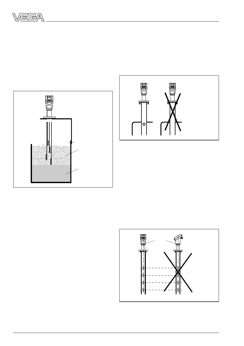
Foam generation
Conductive
foam
Liquid
Mounting and installation
Provide preventative measures against foam
or measure in a bypass tube. Check, if nec-
essary, the possibility of using a different
measurement technology, e.g. capacitive
electrodes or hydrostatic pressure transmit-
ters.
In many cases, VEGAPULS 54 radar sensors
with 5.8 GHz operating frequency achieve
considerably better and more reliable meas-
uring results in foam applications than series
40 sensors with 26 GHz technology.
Foam generation
Conductive foam is penetrated to different
depths by the radar signals and generates a
number of individual (bubble) echoes. At the
same time, the signals are damped in foam,
similar to the way heat radiation is damped
by Styrofoam. Thick, dense, creamy and
conductive foam can cause incorrect meas-
urements.