Figure 11 and, Figure 12), Increases. figure 11 and figure 12 – VEGA FL SWITCH SFN… User Manual
Page 12: Figure 11, figure 12, and figure 13 display traf
FL SWITCH SFN…
2732_en_D
PHOENIX CONTACT
12
direction, i.e., security images from a camera to the
network, with only a few, normal size transmissions
containing control commands going the opposite
direction.
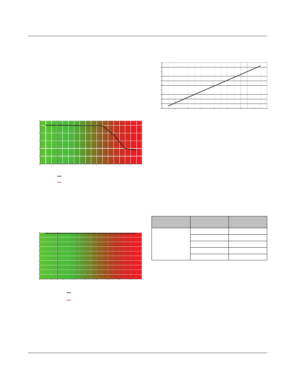
Bidirectional data transfer guidelines
When using jumbo frames for bidirectional data transfers,
the generation of pause frames starts at 3000-byte size
frames. Traffic loadings of near 100% are possible with
frame sizes up to 7000 bytes. Above 7000 bytes the percent
traffic loading has to be reduced to prevent dropped
packets.
Figure 11
Maximum bidirectional traffic loading per port
(FL SWITCH SFN 8GT)
Unidirectional data transfer guidelines
In applications where the data flow is predominantly in one
direction, such as cameras and vision systems, near 100%
loading is possible using jumbo frames.
Figure 12
Maximum unidirectional traffic loading per port
(FL SWITCH SFN 8GT)
When cascading devices in a trunk topology, up to 18 Mbps
of the available bandwidth is required to support overhead
and pause frame traffic for each link between cascaded
switches.
Figure 13
Overhead/cascaded switch vs. frame size
9.4
Calculating Total Network loading with
cascaded (trunk topology) switches
Because of the buffer size considerations when using jumbo
frames, network bandwidth loading should be planned in
advance to prevent packet loss.
1.
Determine the total application traffic load for the
connected devices.
Add all the traffic loads from each device that will be
connected to the switch and transferred to the main
trunk line. When using cameras or vision systems, the
bandwidth usage per device can be high (see Table 2).
Actual numbers may vary depending on the camera or
device type used.
2.
Add all the application traffic from all connected
switches and compare to the maximum network
capacity.
As the trunk traffic passes from switch to switch, add the
total application device traffic from all the switches. The
traffic load on the trunk ports cannot be greater than the
total bandwidth available (1000 Mbps for gigabit and
100 Mbps for Fast Ethernet ports).
3.
Determine the traffic load for bandwidth consumed by
application overhead and pause frames (see
Figure 13). After the first switch, add this amount for
each additional switch segment.
0
200
400
600
8
00
1000
2000
3
000
4000
5000
6000
7000
8
000
9000
9600
Maximum loading
Pause frame threshold
Frame size (bytes)
Tr
a
ff
ic
l
o
ad
in
g
(
M
bp
s)
0
100
200
3
00
400
500
600
700
8
00
900
1000
2000
3
000
4000
5000
6000
7000
8
000
9000
9600
Maximum loading
Pause frame threshold
Frame size (bytes)
Traf
fi
c lo
ad
ing
(M
bps
)
Table 2
Typical bandwidth load
Typical Camera
Settings
Color Depth
(bits/pixel)
Typical Traffic
Load (Mbps)
60 frames per
second
750 x 640 pixels
per frame
8
182
12
275
16
366
24
550
32
732
0
20
40
60
8
0
100
120
140
160
1
8
0
200
2000
3
000
4000
5000
6000
7000
8
000
9000
Frame size (bytes)
Overhe
ad (Mbps)