8 dimensions, 9 fl switch sfn…gt… jumbo frame support, 1 fl switch sfn…gt… jumbo frame capability – VEGA FL SWITCH SFN… User Manual
Page 11: 2 jumbo frame performance factors, 3 application guidelines, 8dimensions, 9fl switch sfn…gt… jumbo frame support, Fl switch sfn, Figure 10 housing dimensions
FL SWITCH SFN…
2732_en_D
PHOENIX CONTACT
11
and 7 are considered high priority and processed
before packets with a priority level between 0 and 3.
After prioritization the packets are forwarded without
modification.
8
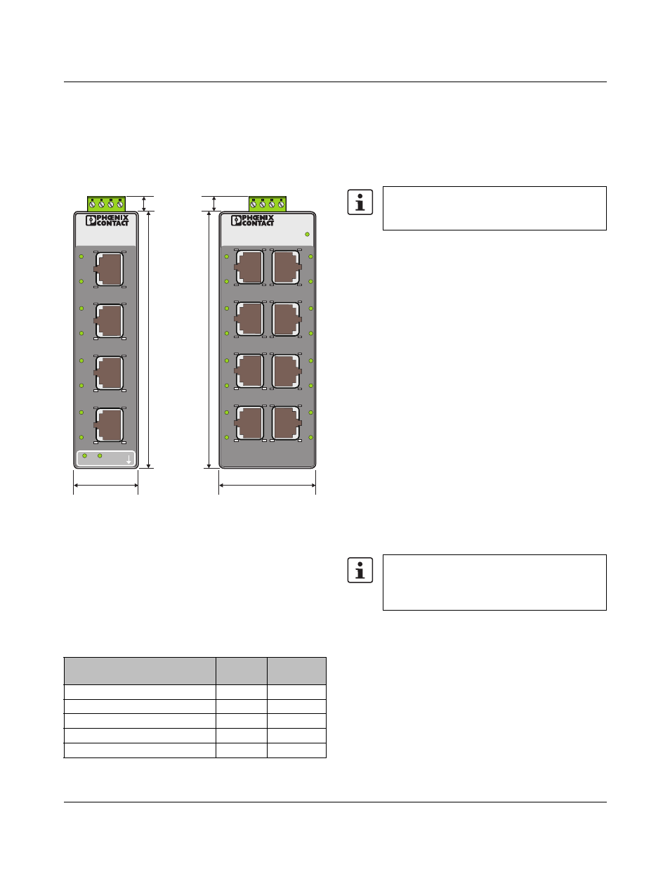
Dimensions
Figure 10
Housing dimensions
9
FL SWITCH SFN…GT… Jumbo
Frame Support
Certain revisions of the FL SWITCH SFN…GT… switches
have the ability to support jumbo frames. Table 1 shows the
minimum version code (V/C) and hardware code (H/C) that
provides jumbo frame support:
A jumbo frame is an Ethernet packet (or frame) which has a
size greater than the IEEE standard 1518 bytes. Jumbo
frames are technically defined as 9000 bytes or less, but
commercial use of the term has been applied to packet
sizes over 9000 bytes. Jumbo frames are used to reduce
network loading when transferring large data files. Fewer
but larger packets, containing fewer overall overhead bytes,
increase the overall network efficiency.
9.1
FL SWITCH SFN…GT… Jumbo Frame
Capability
FL SWITCH SFN…GT… switches support jumbo frames
up to 9600 bytes per frame. In addition, the jumbo frames
can be used with both 100 Mbps and 1000 Mbps
communication. An FL SWITCH SFN…GT… switch has an
Ethernet packet (frame) buffer memory capacity of 16 kB
per port. This memory capacity is especially important when
data is fed through cascaded switches that make up a
network backbone.
9.2
Jumbo Frame Performance Factors
The switch’s frame buffer size, the size of the frames
(bytes/frame) and overall traffic loading of the network
(bandwidth) impact the overall application performance. In
the following sections, the loading per port is compared with
the maximum frame size. At packet (frame) sizes over
3000 bytes, the switch will start sending pause frames to
control the traffic flow (see vertical line on Figure 11 and
Figure 12). As the size of the frame increases, the sending
of pause frames increases. Figure 11 and Figure 12
indicate the maximum loading per port that can occur (for
each jumbo frame size) until the buffer is overloaded and
packets start to be dropped.
9.3
Application Guidelines
The use of jumbo frames in industrial applications typically
falls into two major application classes:
–
Bidirectional data transfers: usually caused by larger
data file exchanges between controllers or PC
applications. These may use jumbo frames in both
directions (read/write) between the industrial devices.
–
Unidirectional data transfer: typically found in networks
where security cameras or vision inspection equipment
feed back to a centralized monitoring station. In these
cases, the vast majority of the traffic flows in one
Table 1
Jumbo Frame Support Firmware
Type Code
Version
Code
Hardware
Code
FL SWITCH SFN 8GT
02
12
FL SWITCH SFN 7GT/SX
03
13
FL SWITCH SFN 6GT/2SX
02
12
FL SWITCH SFN 6GT/2LX
02
12
FL SWITCH SFN 6GT/2LX-20
01
11
X1
X2
X
3
X4
FL
S
WITCH
S
FN 5TX
Ord.-No.: 2
8
91152
100
LNK/
AC
T
100
LNK/
AC
T
100
LNK/
AC
T
100
LNK/
AC
T
LNK/ACT
100
X5
X1
X
3
X5
X7
FL
S
WITCH
S
FN
8
TX
Ord.-No.: 2
8
91929
100
LNK/
AC
T
100
LN
K/
AC
T
100
LNK/
AC
T
100
LNK/
AC
T
US
X2
X4
X6
X
8
100
LNK/
AC
T
100
LNK/
AC
T
100
LNK/
AC
T
100
LNK/
AC
T
14 mm
120 mm
3
0 mm
50 mm
Version codes are displayed on the package label
and Hardware Codes are displayed on the
product label.
Figure 11, Figure 12, and Figure 13 display traffic
loading for 1000 Mbps (gigabit) data rates. For
100 Mbps data rates divide the y axis numbers
by 10.