Introduction terminal description – V-Tech SC6M Manual User Manual
Page 2
Introduction
Terminal Description
The SC6M module is designed to DT system for the purpose of public memory
sharing,staircase light control,and extra cameras extended. Note that the SC6M
unit is just for the monitors that support the function only, it must use together
with PC6 to support these functions, and one unit system just use one SC6M
only.
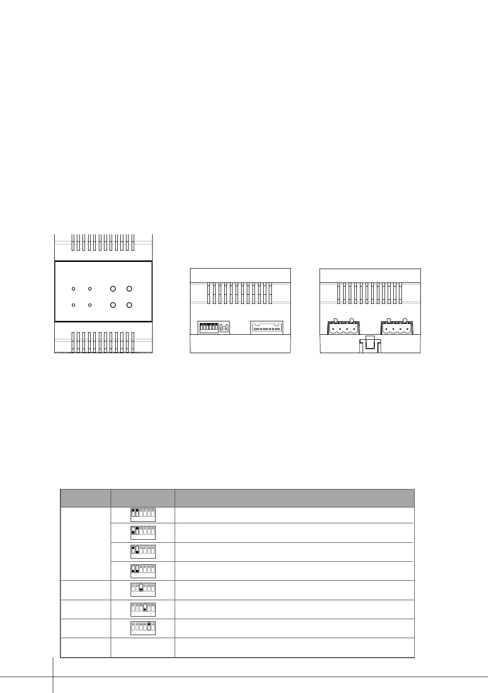
1 2 3 4 5 6
ON
SETUP
RS485
CN1
VD
CAM1 CAM2
SETUP:DIP switches,refer to table 1 for detail information.
RS485:Used to update program for SC6M.
CN1:Input port,connect to PC6.
VD:Output port,connect to DVR.
CAM1:Output port,connect to DT-CAM1(2 wire camera).
CAM2:Output port,connect to DT-CAM2(2 wire camera).
Table1
1 2
3 4 5 6
ON
1 2
3 4 5 6
ON
1 2
3 4 5 6
ON
1 2
3 4 5 6
ON
1 2
3
4 5 6
ON
1 2
3
4
5 6
ON
1 2
3 4
5
6
ON
Bit
DIP1~DIP2
Default setting,ID=0(00),if the system have not any camera controller(SC6),set to 0.
ID=1(10),set to the first camera controller.(SC6)
ID=2(01),set to the second camera controller(SC6).
ID=3(11),set to the third camera controller(SC6).
OFF is default,if the system connect camera1,it should set to ON to activate the camera1
function.
OFF is default,if the system connect camera2,it should set to ON to activate the camera2
function.
OFF is default,if the system connect light,it should set to ON to activate the light function.
Reserve
Reserve
DIP3
DIP4
DIP5
DIP6
Bit State
Description
-1-