Frontpanel, Specifications – Velleman LAB1 User Manual
Page 7
7
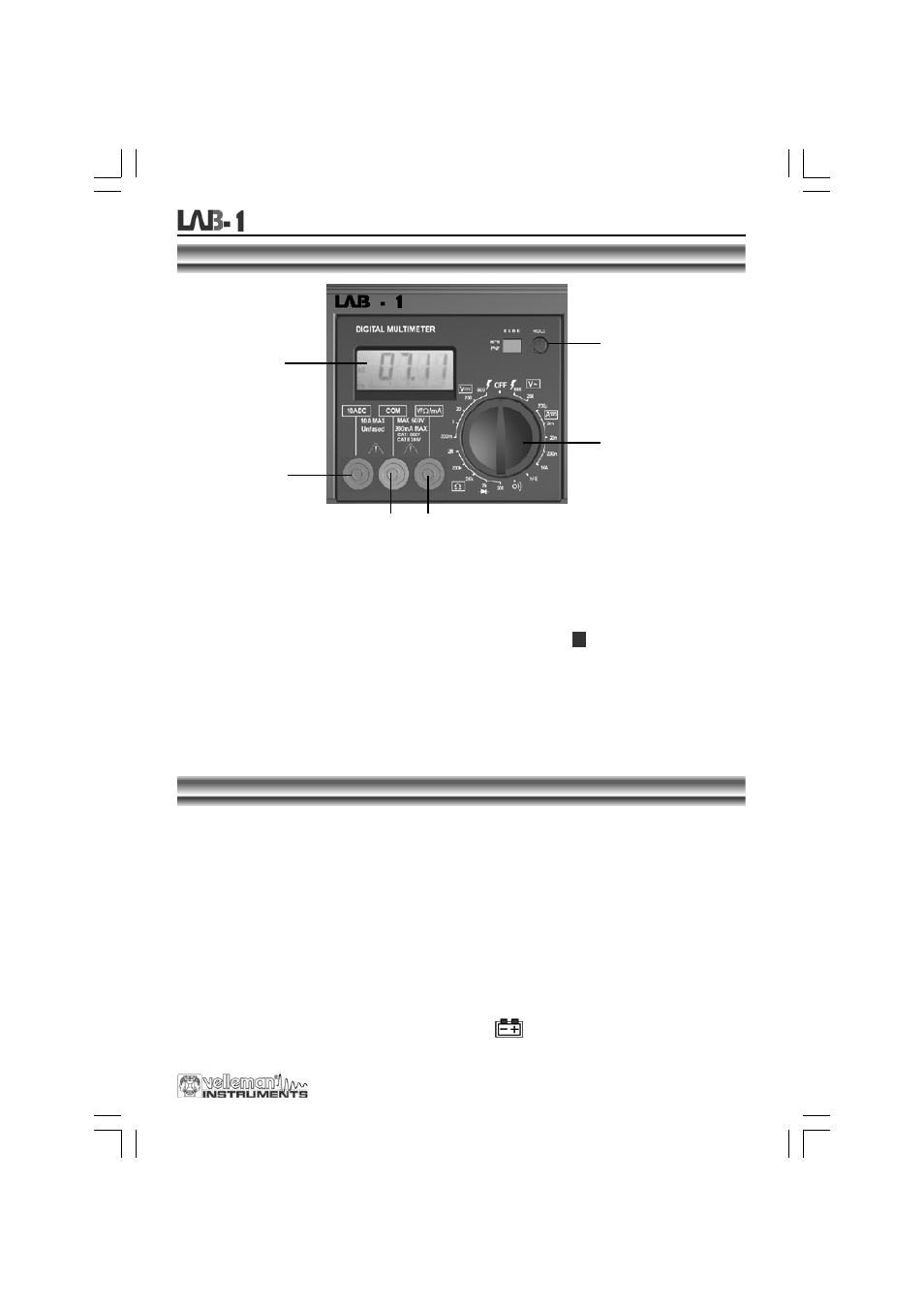
FRONTPANEL
DESCRIPTION OF THE CONTROL PANEL
:
1
Display with backlight
(the backlight is only on when the complete unit is switched ON at the back)
3 ½ digits, 7 segments, LCD: 15mm high
2
Rotary switch
This switch is used to select functions and desired ranges as well as to turn the meter on/off.
3
Hold button
Upon pushing this button, the display will retain the last reading and the "
"-symbol will remain on the
LCD until the button is pushed again.
4
"10A" jack
Insert the red test lead in this connector in order to measure a max. current of 10A.
5
"COM" jack
Insert the black (negative) test lead.
6
"V
ΩmA" jack
Insert the red (positive) test lead in this connector to measure voltage, resistance and current (except 10A).
H
SPECIFICATIONS
Maximum accuracy is achieved during a one-year period after calibration. The ideal set of circumstances requires a
temperature of 18 to 28°C (64°F to 82°F) with a maximum relative humidity of 80%.
Maximum voltage between terminals and earth ground
CAT I 600V or CAT II 300V
Fuse protection
F 200mA / 250V
Power 9V
battery
Display
LCD, 1999 counts, updates 2-3/sec.
Measuring method
Dual-slope integration A/D converter
Overrange indication
Only figure "1" on the display
Polarity indication
"-" displayed for negative polarity
Operating temperature
0 to 40°C
Storage temperature
-10°C to 50°C
Low battery indication
"
" appears on the display
Digital multimeter
1
4
5 6
2
3