Velleman projects K7302 Assembly instructions User Manual
Page 7
7
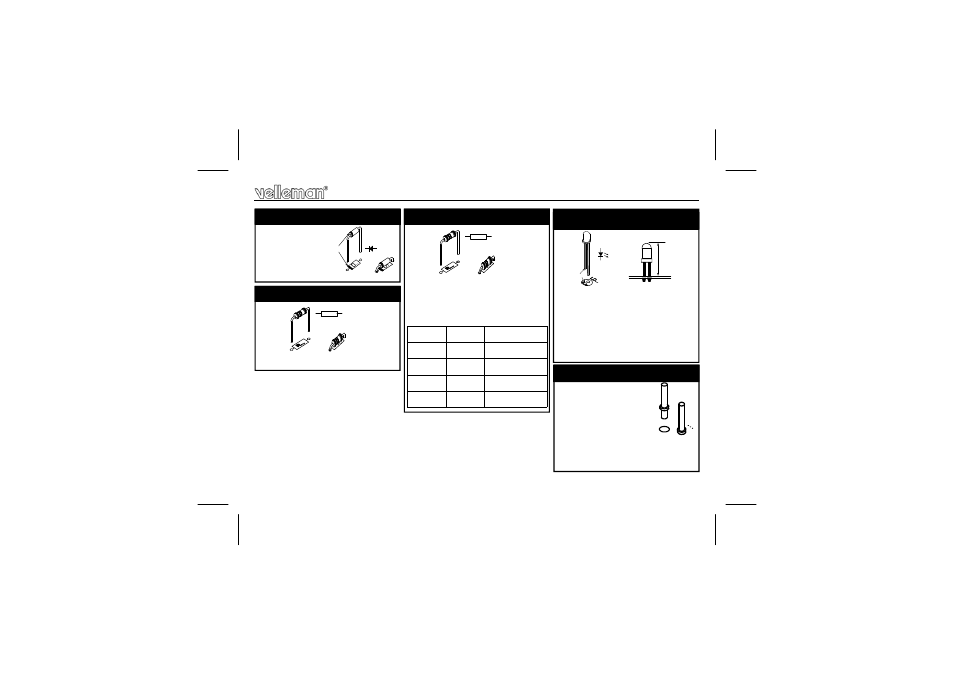
R1 : 120 (1 - 2 - 1 - B - 9).
2.
1/2W
Resistor
R...
Construction
D1 : 1N4007
1. Diode. Watch the polarity !
D...
CATHODE
LD1 : 3mm low current RED
REMARK: Depending on the
used housing, the LED can be
mounted at a higher position, to
make it visible through a hole in
the housing.
4. LED (check the polarity!)
The value of resistor R2 deter-
mines the charge current:
R2
3. Resistor
R...
50mA
47
1/4W
(4 - 7 - 0 - B)
100mA
18
1/4W
(1 - 8 - 0 - B)
200mA
6,8
1/4W
(6 - 8 - B - B)
300mA
3,9
1/2W
(3 - 9 - B - B - 9)
400mA
2,7
1/2W
(2 - 7 - B - B - 9)
:
:
:
:
:
LD...
CATHODE
10mm
17mm
SK2 : +
SK3 : +
SK2 : -
SK3 : -
To connect the input and
output wires via PCB
tabs, mount pins at posi-
tions SK2 and SK3
5. PCB pins
H7302IP'1.pub
page 7
Friday, July 06, 2012 14:20
- K7000 Assembly instructions (12 pages)
- K8042 Assembly instructions (12 pages)
- EDU10 Assembly instructions (24 pages)
- K2601 Assembly instructions (12 pages)
- K8039 Assembly instructions (20 pages)
- K8090 Assembly instructions (12 pages)
- K4305 Assembly instructions (14 pages)
- K8038 Assembly instructions (16 pages)
- K6714 Assembly instructions (16 pages)
- K8018B Assembly instructions (16 pages)
- K8050 Assembly instructions (20 pages)
- K8063 Infosheet (2 pages)
- VM152 Datasheet (1 page)
- K8006 Assembly instructions (16 pages)
- K8059 Infosheet (1 page)
- KA02 Datasheet (1 page)
- K2570 Assembly instructions (8 pages)
- K7102 Assembly instructions (12 pages)
- EDU08 Datasheet (1 page)
- K8092 Infosheet (1 page)
- K2543 Assembly instructions (12 pages)
- VMA03 Datasheet (1 page)
- MK179 Datasheet (1 page)
- K2579 Assembly instructions (12 pages)
- EDU05 (15 pages)
- K4040 Assembly instructions (28 pages)
- K7203 Assembly instructions (12 pages)
- K8027 Assembly instructions (12 pages)
- K8023 Assembly instructions (20 pages)
- MK195 Datasheet (1 page)
- K8008 Assembly instructions (16 pages)
- K5600R Assembly instructions (14 pages)
- VM110N Datasheet (1 page)
- MK180 Datasheet (1 page)
- MK176 Datasheet (1 page)
- MK190 Datasheet (1 page)
- VM179 Datasheet (1 page)
- K8049 Assembly instructions (12 pages)
- MK153 Assembly instructions (1 page)
- VM8095 Datasheet (1 page)
- VM134 Datasheet (1 page)
- K8077 Infosheet (1 page)
- K5201 Assembly instructions (16 pages)
- K8096 Assembly instructions (16 pages)