Testing the board – Velleman projects EDU05 Assembly instructions User Manual
Page 4
EDU05 Test procedure & programming in Visual Basic 2010 ( Version 1.0)
4
2. Testing the board
Make a connection between the board and PC using the included USB cable. The LCD will display the message
“Press button SW3 ... SW7 to show analog input values SW8 to exit”. I
n the meantime the LEDs will light up in sequence.
LD1 and LD2 are digital inputs.
Press each button and check the LCD readout to check if the board functions correctly.
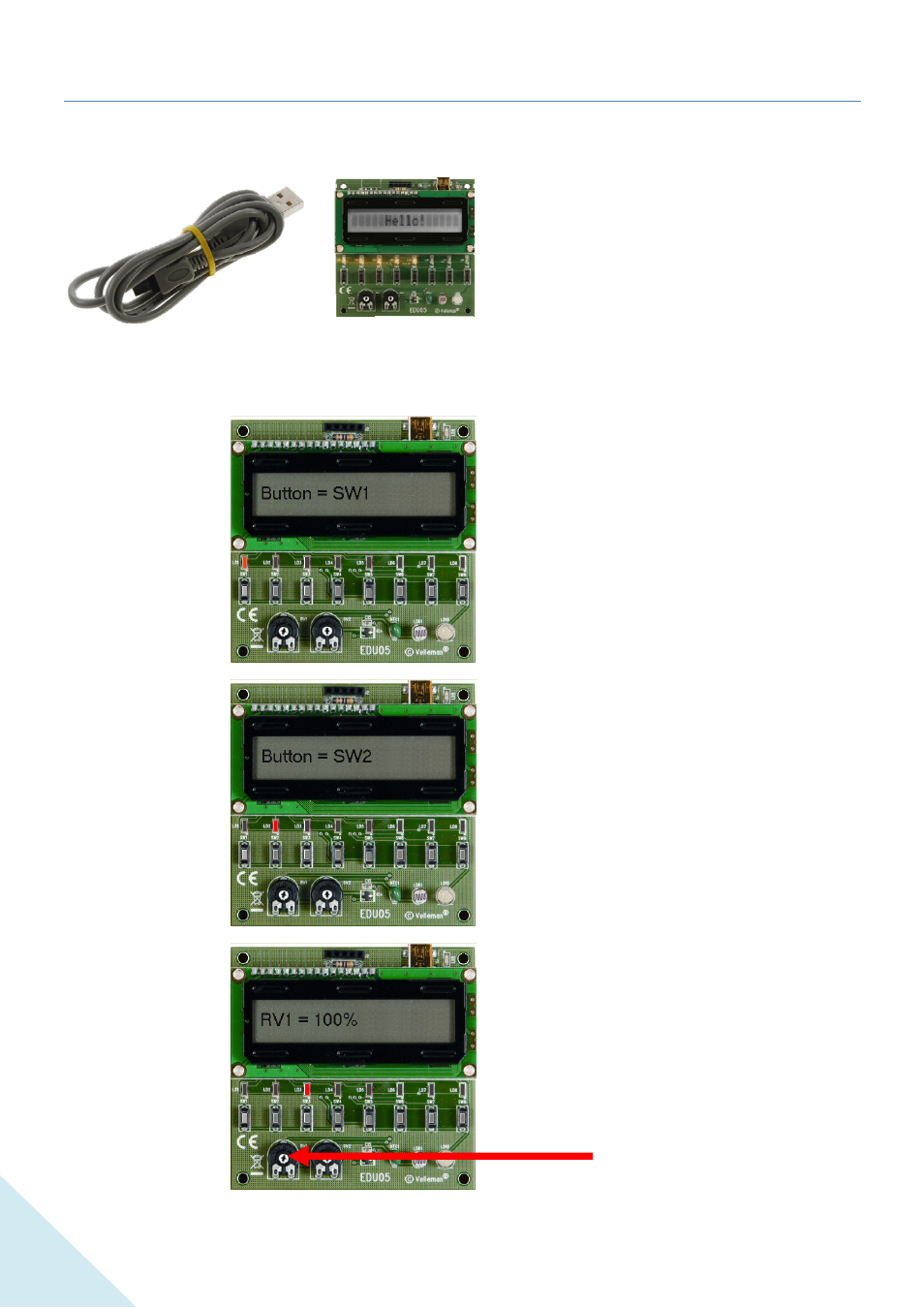
Press button 1 ... 7 one after the other. When you press a button, the corresponding LED lights up, and the LCD
displays the corresponding value
Press button 1
Press button 2
Press button 3
Press this button to read the value of
potentiometer 1.
When you adjust the potentiometer, the
value on the display changes.
Potentiometer 1