Spicer CTIS (Central Tire Inflation System) Troubleshooting Guide User Manual
Page 47
44
Service Codes
PCU Solenoid (Codes 51,
52, 54, 55, 56)
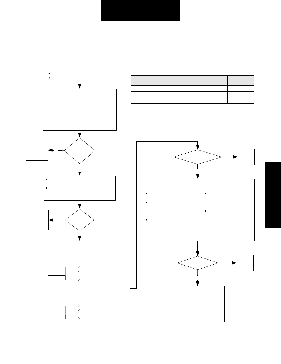
PCU Solenoid (Codes 51, 52, 54, 55, 56)
1. Disconnect ECU harness connector.
2. Check for continuity between:
PCU Solenoid Harness
ECU Harness
Connector Pin
Connector Pin
F (flange round connector)
G (M939 round connector)
A
or
K2 (rectangular connector)
3. On 1-channel systems, also check for continuity between:
PCU Solenoid Harness
ECU Harness
Connector Pin
Connector Pin
F (round connector)
W (M939 round connector)
B
or
K2 (rectangular connector)
4. Check continuity of harness pin(s) shown in table for given
service code (PCU harness connector to ECU harness connector).
Replace ECU.
Note: ECUs are not a typical cause
of problems. If an ECU is replaced,
the system should be carefully
rechecked to make sure the problem
has been fixed and does not reoccur.
No
Use diagnostic tool to identify which solenoid
to troubleshoot.
Switch off ignition.
Disconnect harness at PCU connector.
Measure solenoid coil resistance on PCU connector
for identified coil. Resistance should be 30-80 ohms.
On 1-Channel Systems On 2-Channel Systems
Control: B – D Control: A – D
Deflate: A – E
Deflate: A – E
Supply: A – F
Supply: A – F
Front: A – C
Rear: A – B
Are
resistance
measurements
OK?
Check for shorts between PCU connector
pins D, E, F and vehicle ground.
On 2-channel systems, check for shorts
between PCU connector pins C, B and
vehicle ground.
Are any
pins shorted
to ground?
Are circuits continuous?
Repair or
replace
harness.
Are connections OK?
Repair or
replace
connections,
coils or PCU.
Repair or
replace
connections,
coils or PCU.
No
Yes
No
Yes
Yes
No
Yes
Each code matches one specific solenoid. When the troubleshooting
instructions refer to connector test points, use chart to select the pin
test point for use with the particular fault code you are diagnosing.
Fault Code
Supply
(51)
Deflate
(52)
Control
(54)
Front
(55)
Rear
(56)
PCU Harness Connector
ECU Harness Connector (round)
ECU Harness Connector (rectangular)
F
E
D
C
B
B
C
R
D
A
B1
B2
B3
D1
D2
Repair or
replace
harness.
Non-M939 Style Vehicle
On 1-channel systems, verify
continuity between A and B.
Verify no continuity between
any combination of pins D, E, F
on PCU harness connector and
A on PCU harness connector.
On 2-channel systems, verify
no continuity between any
combination of pins C or B on
PCU harness and pin A on
PCU harness.
M939 Style Vehicle
Verify no continuity between
D, E, F on PCU harness
connector and A on PCU
harness connector.
Verify no continuity between
D, E, F on PCU harness
connector and B on PCU
harness connector.
Measure at PCU harness connector.