Slip member and boot installation, Driveshaft installation – Spicer Driveshafts Service Manual User Manual
Page 29
26
Driveshaft
Installation
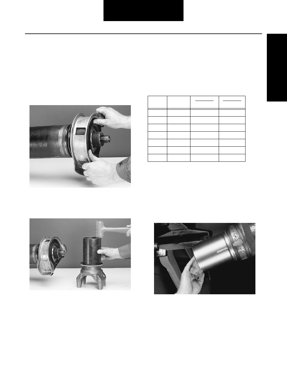
Note: If the application requires the installation of a slinger,
avoid damage during installation.
Note: Do not reuse old slingers. Most replacement center
bearings will not include slingers.
3.
Carefully align the new center bearing assembly with
the ground surface of the midship tube shaft. Physi-
cally push the center bearing onto the midship tube
shaft.
4.
Press remaining slinger on end yoke using a section
of tubing to avoid damaging slinger.
5.
Using a soft-faced hammer, drive the yoke onto mid-
ship tube shaft, making sure phasing marks from
driveshaft removal procedure are in line. Continue to
tap the yoke until it is completely seated against the
center bearing.
Note: Only drive (press) off the washer face of the yoke. Never
hammer or press on the ears of the yoke. See illustra-
tion
6.
Install a washer (if required) and new midship nut
and torque nut to specifications. See midship nut
specifications, Table MM.
Failure to torque midship nut to required specifications can
cause driveline failure, which can result in separation of the
driveline from the vehicle. A separated driveline can result in
property damage, serious personal injury or death.
Slip Member and Boot Installation
1.
Clean ALL grease from yoke shaft and spline sleeve.
Make sure grease-cutting solvent does not intrude
into the tube through the vent hole in the spline
sleeve plug. Be sure the phasing marks made during
disassembly are not removed.
Table MM - Midship Nut Specifications
Series
Head Size*
Nut Torque
Nm
Nut Torque
LB. FT.
SPL55
1 5/16"
542-610
400-450
SPL70
1 5/8"
644-712
475-525
SPL90
1 5/8"
644-712
475-525
SPL100
1 5/8"
644-712
475-525
SPL140
41mm*
644-712
475-525
SPL170
41mm*
644-712
475-525
SPL250
41mm*
644-712
475-525