Center bearing installation, Driveshaft – Spicer Driveshafts Service Manual User Manual
Page 28
25
Driveshaft
3.
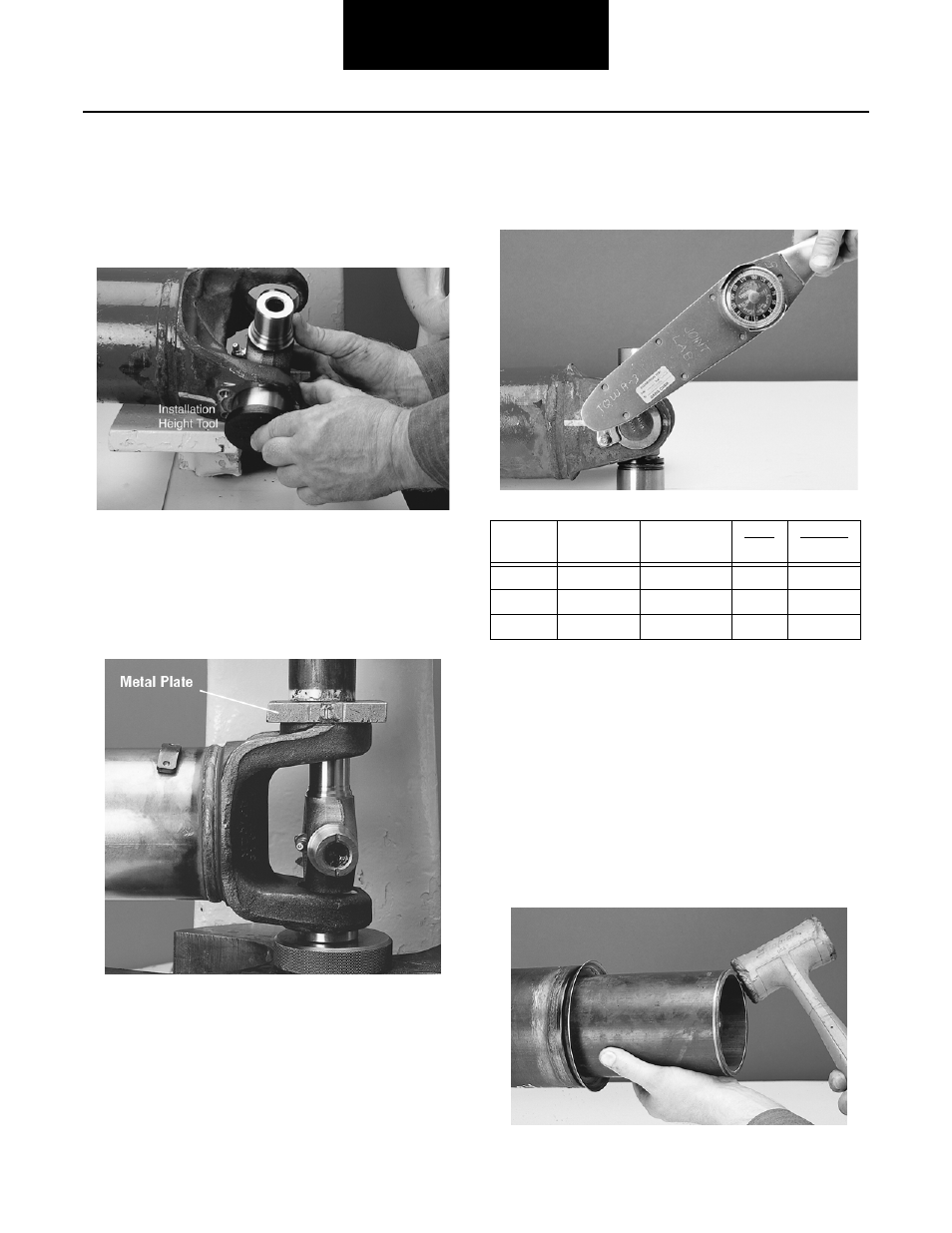
Move one end of the journal cross to cause a trun-
nion to project through the cross hole beyond the
outer machined face of the yoke ear. Take one bear-
ing cup assembly and position an installation height
tool on the end of the bearing cup assembly. Place
the bearing cup assembly over the protruding trun-
nion diameter and align it to the yoke cross.
4.
Align the yoke in an arbor press with the bearing
assembly resting on the base of the press. Cover the
yoke ear with a metal plate that has 0.25 inch (6.4
mm) minimum thickness. Push the yoke onto the
bearing cup assembly until it is flush with the cross
hole face. Do not remove the installation height
tool.
5.
Flip yoke 180 degrees. Position the remaining
installation heigh tool on the end of another bearing
cup assembly. Place bearing cup assembly over
trunnion diameter and align it to the yoke cross hole.
Push the bearing cup assembly until both installation
height tools are flush with the cross hole face.
6.
Install new spring tabs and 8mm thread bolts. Make
sure that no grease or foreign material is present
between the contact areas of the spring tabs, bearing
cups and yoke cross hole faces. Tighten bolts to the
required torque.
*Bolts are specially heat-treated.
DO NOT substitute inferior grade bolts.
Center Bearing Installation
1.
Wipe the bearing surface of the midship tube shaft
with a fine emery cloth.
2.
Install a new slinger (included in center bearing
replacement kit) on the midship tube shaft using a
section of tubing to avoid damaging slinger. Make
sure the slinger is completely seated against the
midship tube shaft shoulder
SPRING TAB BOLT SPECIFICATIONS
SERIES
THREAD
SIZE
HEAD SIZE
BOLT
Nm
TORQUE
LB. FT.
SPL140
8mm x 1.00
8mm, 6 point
34-41
25-30
SPL170
8mm x 1.00
8mm, 6 point
34-41
25-30
SPL250
8mm x 1.00
8mm, 6 point
34-41
25-30