Remove wheel differential (all standard models) – Spicer Single Drive Axles Service Manual: S170, S190, S590 User Manual
Page 15
11
Carrier Assembly
Remove Wheel Differential (All Standard Models)
Carrier Disassembly
For models having the wheel differential lock option or a
carrier thrust bolt, refer to the following procedure. These
parts must be removed first before further disassembly of
the wheel differential can take place.
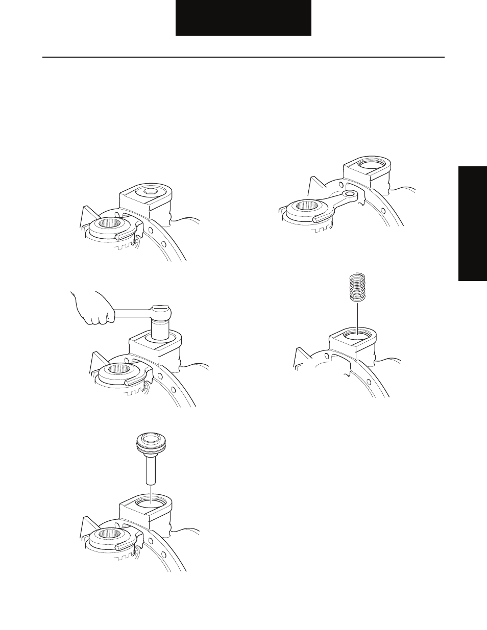
1. For ease of service, mount differential carrier in
head stand with differential locked with the differ-
ential lock facing up.
2. Remove the threaded cylinder cap.
3. Remove the piston push rod from the shift fork.
4. Remove the shift fork and sliding clutch assembly.
Note: Do not disassemble the shift fork from the sliding
clutch unless parts are to be replaced. To disassem-
ble, use a pin punch to remove spring pin from the
fork leg. The sliding clutch can now be removed from
the fork.
5. Remove the shift fork spring.
Note: Omit this step if the ring gear is to be replaced. If the
ring gear is to be reused, check the tooth contact pat-
tern and ring gear backlash before disassembling the
carrier assembly. When checking the backlash, a yoke
or helical gear must be installed and torqued to the
proper specification to get an accurate reading. Best
results are obtained when tooth contact patterns are
maintained in used gearing.
Carrier A
ssembly