Appendix, A.1 4-20 ma current loop option – American Magnetics 135 & 136 Liquid Helium Level Instruments (CE-Marked) User Manual
Page 67
Rev. 3
55
Appendix
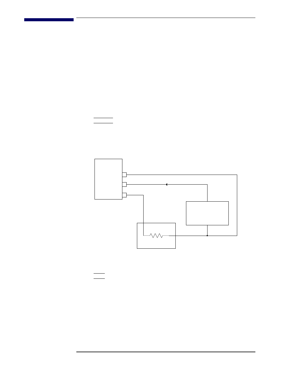
A.1 4-20 ma Current Loop Option
The 4-20 mA output utilizes pins 1 and 2 of connector J2. When the Model
135/136 is configured for the 4-20 mA current loop option, the 0-10 VDC
analog output from connector J2 is not available. The figure below shows
the wiring diagram and the voltage requirements for the power supply and
receiver.
Caution
It is extremely important to observe all polarities and to not exceed
+32 VDC for the loop power supply in order to prevent damage to the
4-20 mA driver circuit.
Note
For maximum immunity to external electrical and electromagnetic
disturbances, all external cabling (except for the AC input and
controller output) should be shielded. The cable shield should be
connected to the chassis of the instrument by connecting to the D-sub
connector shell.
Receiver
AMI
Level
Instrument
Loop
Power
Supply
+13 to +32 VDC
R
L
I
LOOP
J2 pin 1 (+)
+
+
_
_
J2 pin 2 (-)
J2 pin 4 (common)