Installation – American Magnetics 4Q06125PS-430 Integrated Power Supply System User Manual
Page 32
14
Rev.
5
Installation
Power Requirements
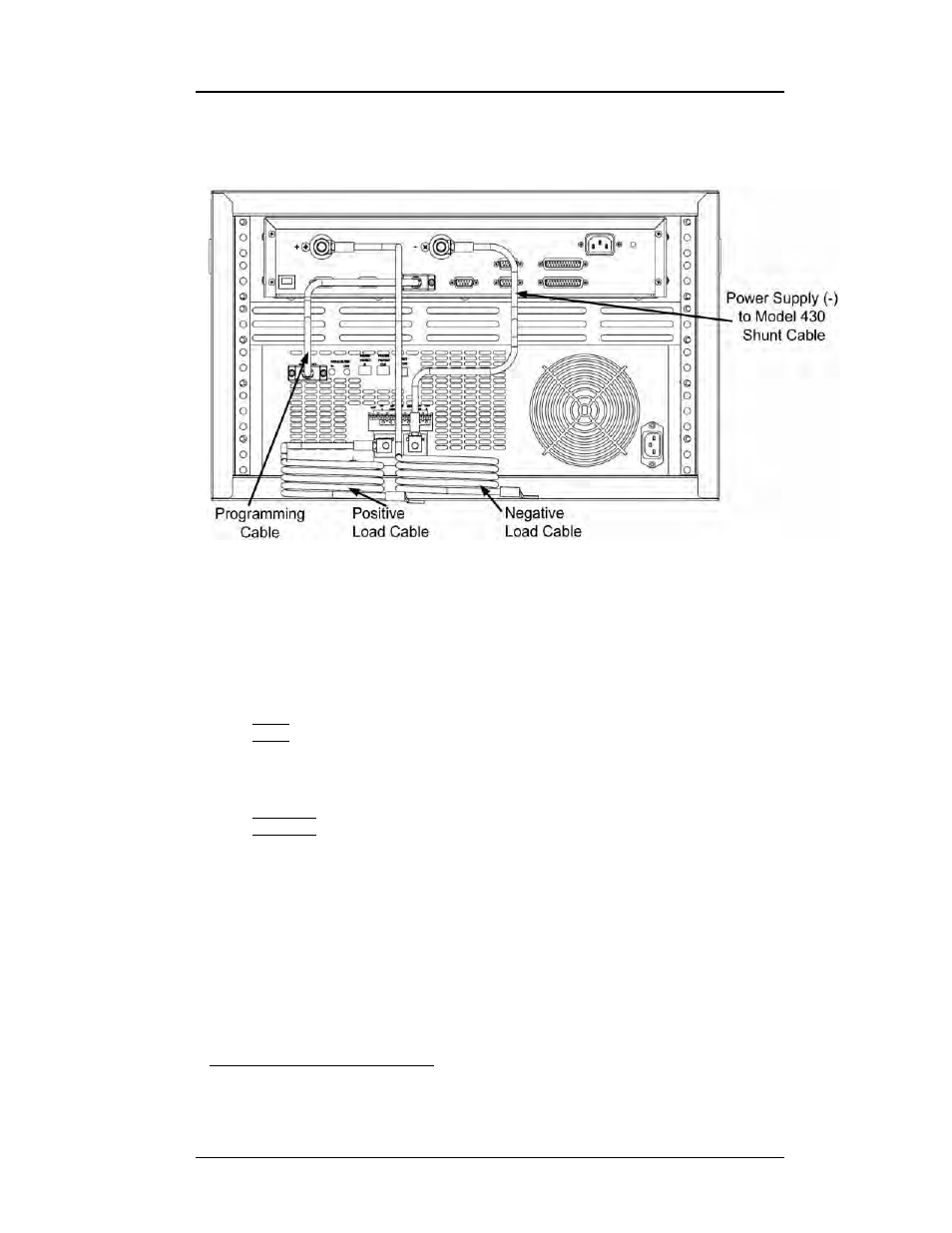
interconnects for the AMI Model 4Q06125PS-430 Power Supply system.
Refer to Figure 2-1 for a physical view of the interconnects.
Refer to Figure 2-2 on page 15. Ensure the cabling is connected in the
following manner
1
:
a. Connect the power supply
OUTPUT terminal (1) to the positive
magnet current lead (2).
Note
The use of locking hardware is recommended for all high-current
connections.
Caution
Do not overtighten the hardware on the interconnection terminals
(refer to specifications table on page 8 for torque limits).
Overtightening can result in damage to the terminals.
b. Connect the negative magnet current lead (3) to the positive (+)
resistive shunt terminal (4) on the back of the Model 430
Programmer.
1. Some connections take more than one cable - read the complete procedure before
beginning.
Figure 2-1.
Typical Model 4Q06125PS-430 System Rack Interconnections