Table 3-1. led color legend, Plate sensor contamination, Operation – American Magnetics 188CPS Point-Sensing Instrument User Manual
Page 21
20
Operation
Sensor contamination
3.
Observe the state of the front panel LEDs and rear panel relay contact pairs
When a plate sensor is immersed in liquid, the corresponding front panel LED will
energize as a green color and the rear panel relay contact pair will close. If a plate
sensor is exposed to gas, the corresponding front panel LED will energize as an amber
color and the rear panel relay contact pair will open.
Note
Rear panel input OSC1 corresponds to the front panel SENSOR 1 LED, input
OSC2 corresponds to the SENSOR 2 LED, etc. The rear panel relay contact
pairs are also ordered from 1 to 5 corresponding to the OSC1 through OSC5
inputs.
If valid MIN and/or MAX calibration data is not available for a sensor input, then the
corresponding LED will always be de-energized (OFF) and the corresponding relay
contact pair will remain open at all times.
If a previously calibrated sensor input becomes shorted or disconnected, the
corresponding LED will energize as a red color within 5 seconds of the fault
occurrence. The state of the relay contact pair is unchanged from the last valid
measurement.
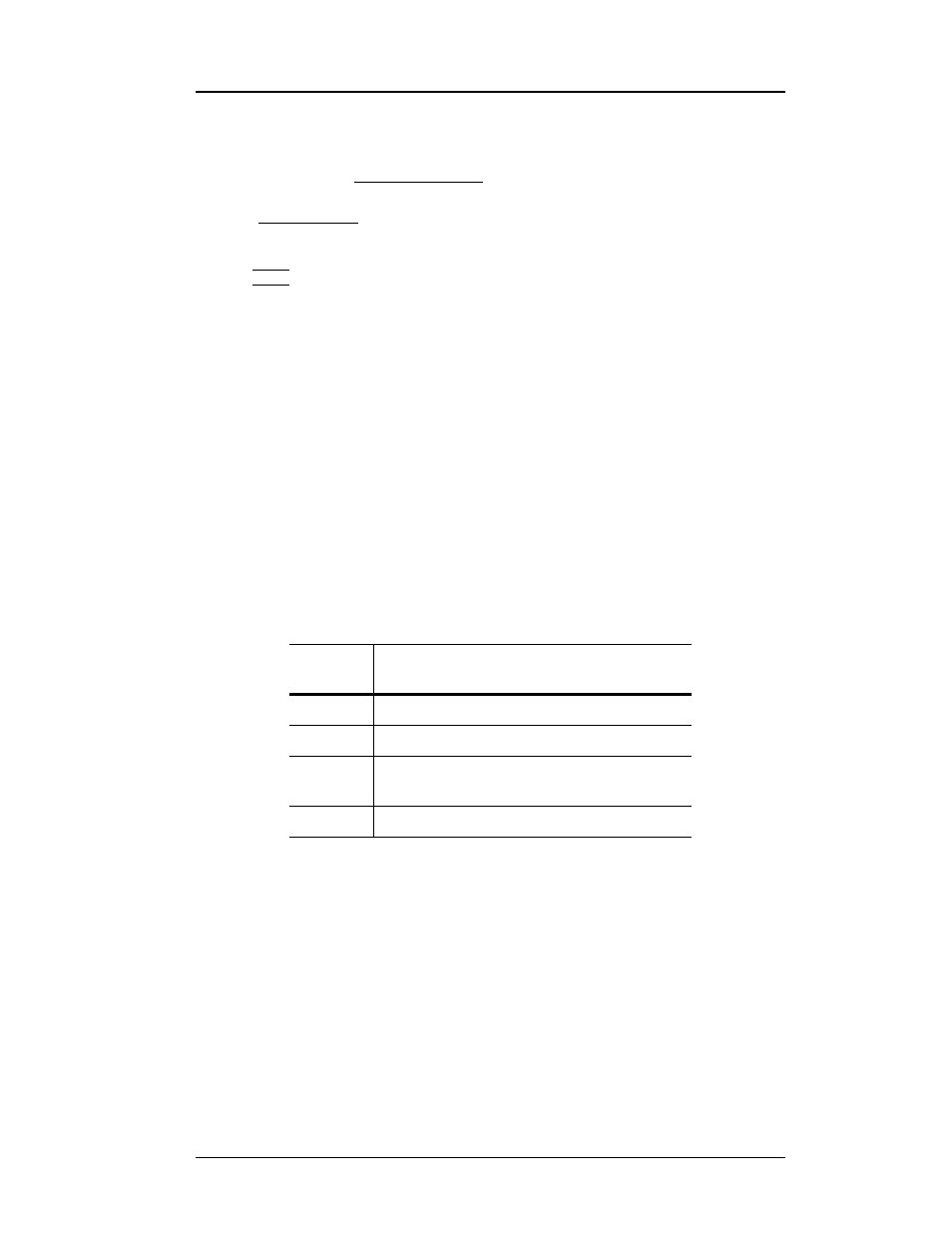
The meaning of the LED color for a corresponding sensor input is summarized in the
following table:
Plate sensor contamination
To ensure proper instrument calibration and operation, care must be taken to ensure
each plate sensor is kept free of contaminants and not subjected to any force which
would physically distort the sensor. Water or other electrically conducting substances
in the sensor will disturb the measured capacitance and therefore instrument response.
Physically distorting the sensor in any way will also cause abnormal instrument
operation by introducing variations in the sensor capacitance not due to liquid level.
The calibration of the instrument can also be inaccurate if care is not taken to ensure
the sensor is in a proper environment.
LED
Color
Condition
Green
Sensor is immersed in liquid.
Amber
Sensor is exposed to gas.
Red
Sensor or oscillator cable is shorted, or
oscillator has failed or has been disconnected.
OFF
MIN and/or MAX calibration data not available.
Table 3-1. LED color legend.