Assembly – Bosch GWS 14-125 Inox Professional User Manual
Page 18
English | 19
Bosch Power Tools
1 609 92A 069 | (20.2.13)
Technical Data
Noise/Vibration Information
Measured sound values determined according to EN 60745.
Typically the A-weighted noise levels of the product are:
Sound pressure level 91 dB(A); Sound power level
102 dB(A). Uncertainty K =3 dB.
Wear hearing protection!
Vibration total values a
h
(triax vector sum) and uncertainty K
determined according to EN 60745:
Surface grinding: a
h
= 4.5 m/s
2
, K=1.5 m/s
2
,
Disk sanding: a
h
= 3.0 m/s
2
, K=1.5 m/s
2
.
The vibration emission level given in this information sheet
has been measured in accordance with a standardised test
given in EN 60745 and may be used to compare one tool with
another. It may be used for a preliminary assessment of expo-
sure.
The declared vibration emission level represents the main ap-
plications of the tool. However if the tool is used for different
applications, with different accessories or poorly maintained,
the vibration emission may differ. This may significantly in-
crease the exposure level over the total working period.
An estimation of the level of exposure to vibration should also
take into account the times when the tool is switched off or
when it is running but not actually doing the job. This may sig-
nificantly reduce the exposure level over the total working pe-
riod.
Identify additional safety measures to protect the operator
from the effects of vibration such as: maintain the tool and the
accessories, keep hands warm, organise work patterns.
Declaration of Conformity
We declare under our sole responsibility that the product de-
scribed under “Technical Data” is in conformity with the fol-
lowing standards or standardization documents: EN 60745
according to the provisions of the directives 2011/65/EU,
2004/108/EC, 2006/42/EC.
Technical file (2006/42/EC) at:
Robert Bosch GmbH, PT/ETM9,
D-70745 Leinfelden-Echterdingen
Robert Bosch GmbH, Power Tools Division
D-70745 Leinfelden-Echterdingen
18.01.2013
Assembly
Mounting the Protective Devices
Before any work on the machine itself, pull the mains
plug.
Note: After breakage of the grinding disc during operation or
damage to the holding fixtures on the protection guard/power
tool, the machine must promptly be sent to an after-sales ser-
vice agent for maintenance for addresses, see section “After-
sales Service and Application Service”.
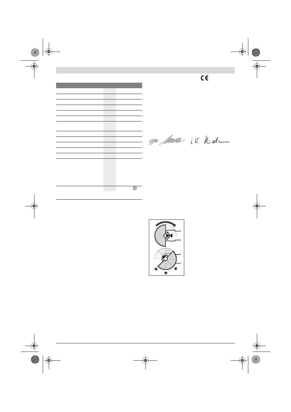
Protection Guard for Grinding
Place the protection guard 12 on-
to the spindle collar as shown in
the illustration. The triangle marks
on the protection guard must cor-
respond with the respective
marks on the gear case.
Press the protection guard 12 on-
to the spindle collar until the
shoulder of the protection guard
is seated against the flange of the
machine, and turn the protection
guard until it can clearly be heard
to engage.
Adjust the position of the protection guard 12 to the require-
ments of the work process. For this, press the release lever 1
upward and turn the protection guard 12 to the required po-
sition.
Adjust the protection guard 12 in such a manner that
sparking is prevented in the direction of the operator.
The protection guard 12 may be turned only upon actu-
ation of the release lever 1! Otherwise the power tool
may not continue to be used under any circumstances
and must be taken to an after-sales service agent.
Note: The encoding keys on the protection guard 12 ensure
that only a protection guard that fits the machine type can be
mounted.
Angle Grinder
GWS 14-125 Inox
Article number
3 601 H29 ...
Rated power input
W
1400
Output power
W
820
Rated speed
min
-1
2200 – 7500
Grinding disc diameter, max.
mm
125
Thread of grinder spindle
M 14
Thread length (max.) of grinder
spindle
mm
22
Kickback stop
Restarting Protection
Reduced starting current
Constant electronic control
Speed preselection
Weight according to
EPTA-Procedure 01/2003
– with vibration-damping
auxiliary handle
– with standard-auxiliary
handle
kg
kg
2.2
2.1
Protection class
/
II
The values given are valid for a nominal voltage [U] of 230 V. For differ-
ent voltages and models for specific countries, these values can vary.
Dr. Egbert Schneider
Senior Vice President
Engineering
Helmut Heinzelmann
Head of Product Certification
PT/ETM9
OBJ_BUCH-611-005.book Page 19 Wednesday, February 20, 2013 9:29 AM