Assembly – Bosch GBH 3-28 DRE Professional User Manual
Page 15
English | 15
Bosch Power Tools
1 609 92A 043 | (10.1.13)
GBH 3-28 DRE/GBH 3-28 DFR:
The vibration emission level given in this information sheet has
been measured in accordance with a standardised test given in
EN 60745 and may be used to compare one tool with another.
It may be used for a preliminary assessment of exposure.
The declared vibration emission level represents the main ap-
plications of the tool. However if the tool is used for different
applications, with different accessories or poorly maintained,
the vibration emission may differ. This may significantly in-
crease the exposure level over the total working period.
An estimation of the level of exposure to vibration should also
take into account the times when the tool is switched off or
when it is running but not actually doing the job. This may signif-
icantly reduce the exposure level over the total working period.
Identify additional safety measures to protect the operator
from the effects of vibration such as: maintain the tool and the
accessories, keep hands warm, organise work patterns.
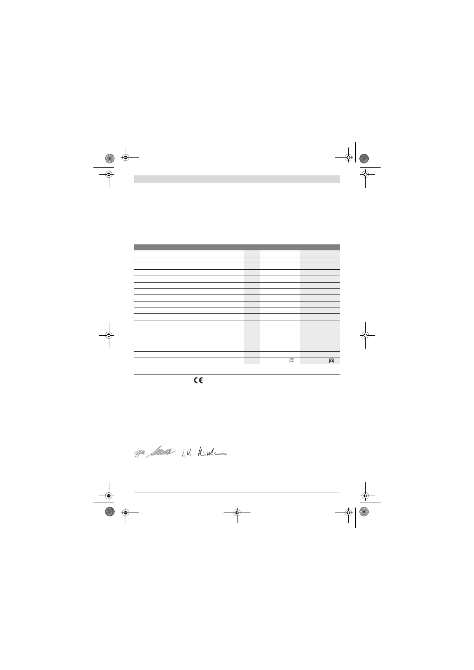
Technical Data
Declaration of Conformity
We declare under our sole responsibility that the product de-
scribed under “Technical Data” is in conformity with the fol-
lowing standards or standardization documents: EN 60745
according to the provisions of the directives 2011/65/EU,
2004/108/EC, 2006/42/EC.
Technical file (2006/42/EC) at:
Robert Bosch GmbH, PT/ETM9,
D-70745 Leinfelden-Echterdingen
Robert Bosch GmbH, Power Tools Division
D-70745 Leinfelden-Echterdingen
Leinfelden, 14.12.2012
Assembly
Before any work on the machine itself, pull the mains
plug.
Auxiliary Handle
Operate your machine only with the auxiliary handle 12.
Changing the position of the auxiliary handle
(see figure A)
The auxiliary handle 12 can be set to any position for a secure
and low-fatigue working posture.
– Turn the bottom part of the auxiliary handle 12 in counter-
clockwise direction and swivel the auxiliary handle 12 to
the desired position. Then retighten the bottom part of the
auxiliary handle 12 by turning in clockwise direction.
Pay attention that the clamping band of the auxiliary handle is
positioned in the groove on the housing as intended for.
Adjusting the Drilling Depth (see figure B)
The required drilling depth X can be set with the depth stop 11.
Rotary Hammer
GBH 3-28 DRE
GBH 3-28 DFR
Article number
3 611 B3A 0..
3 611 B4A 0..
Speed control
Stop rotation
Right/left rotation
Quick change chuck
–
Rated power input
W
800
800
Impact rate
min
-1
0 –4000
0 –4000
Impact energy per stroke according to EPTA-Procedure 05/2009
J
3.1
3.1
Speed
min
-1
0 –900
0 –900
Tool holder
SDS-plus
SDS-plus
Spindle collar diameter
mm
50
50
Permissible drilling diameter, max.:
(also see page 16)
– Concrete*
– Brickwork (with core bit)
– Steel
– Wood
mm
mm
mm
mm
28
82
13
30
28
82
13
30
Weight according to EPTA-Procedure 01/2003
kg
3.5
3.6
Protection class
/
II
/
II
*not suitable with core bit
The values given are valid for a nominal voltage [U] of 230 V. For different voltages and models for specific countries, these values can vary.
Dr. Egbert Schneider
Senior Vice President
Engineering
Helmut Heinzelmann
Head of Product Certification
PT/ETM9
OBJ_BUCH-770-006.book Page 15 Thursday, January 10, 2013 11:11 AM