Z87m extreme4, English – ASRock Z87M Extreme4 User Manual
Page 27
Z87M Extreme4
25
English
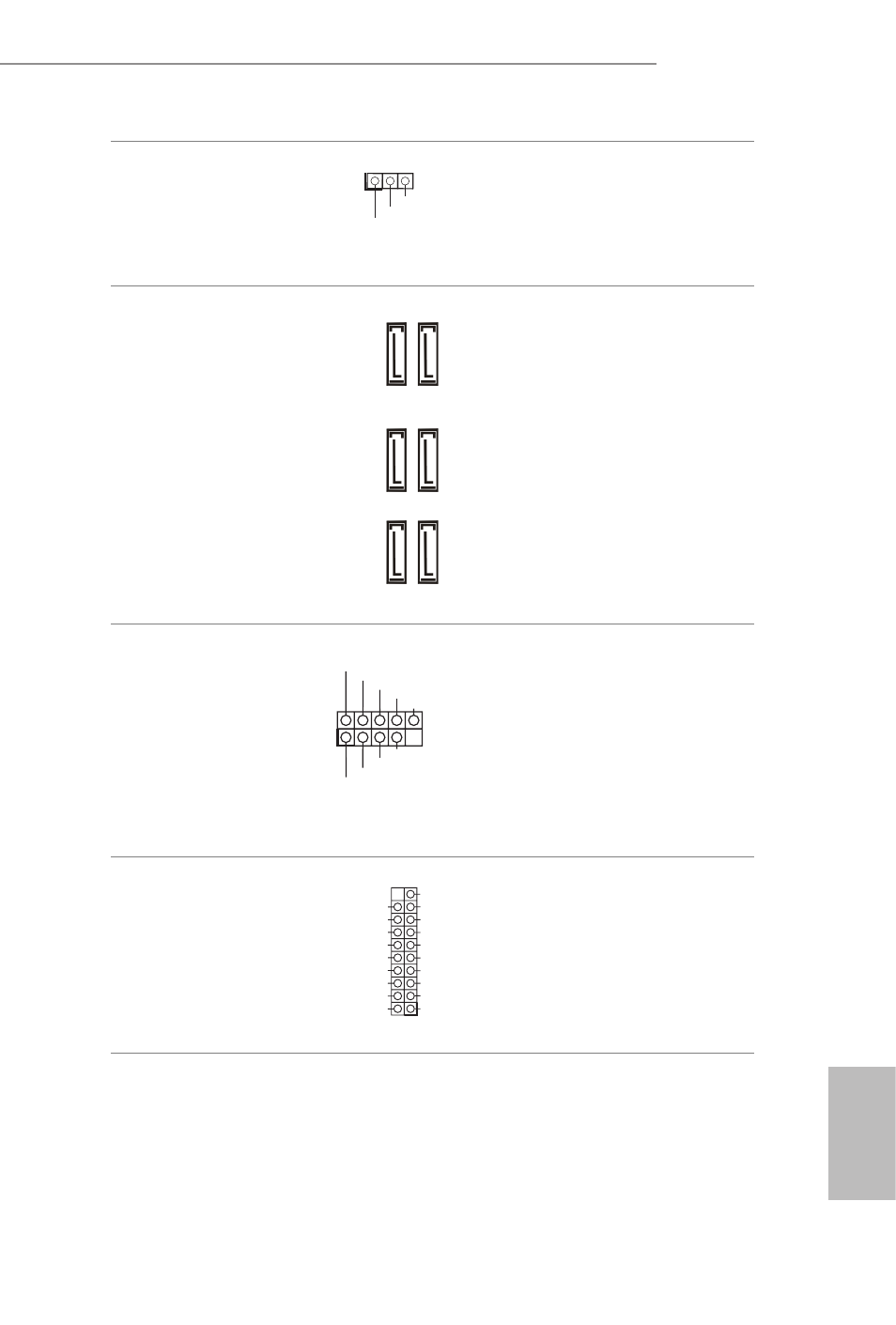
Power LED Header
(3-pin PLED1)
(see p.1, No. 18)
Please connect the chassis
power LED to this header
to indicate the system’s
power status.
Serial ATA3 Connectors
(SATA3_0_1:
see p.1, No. 8)
(SATA3_2_3:
see p.1, No. 9)
(SATA3_4_5:
see p.1, No. 10)
These six SATA3
connectors support SATA
data cables for internal
storage devices with up
to 6.0 Gb/s data transfer
rate. If the eSATA port
on the rear I/O has been
connected, the internal
SATA3_1 will not
function.
USB 2.0 Headers
(9-pin USB4_5)
(see p.1, No. 17)
(9-pin USB6_7)
(see p.1, No. 18)
Besides two USB 2.0 ports
on the I/O panel, there
are three headers on this
motherboard. Each USB
2.0 header can support
two ports.
USB 3.0 Headers
(19-pin USB3_4_5)
(see p.1, No. 7)
Besides four USB 3.0 ports
on the I/O panel, there
are one header on this
motherboard. Each USB
3.0 header can support
two ports.
1
PLED+
PLED+
PLED-
SA
TA3_0_1
SA
TA3_4_5
SA
TA3_2_3
DUMMY
GND
GND
P+
P-
USB_PWR
P+
P-
USB_PWR
1
1
IntA_PB_D+
Dummy
IntA_PB_D-
GND
IntA_PB_SSTX+
GND
IntA_PB_SSTX-
IntA_PB_SSRX+
IntA_PB_SSRX-
Vbus
Vbus
Vbus
IntA_PA_SSRX-
IntA_PA_SSRX+
GND
IntA_PA_SSTX-
IntA_PA_SSTX+
GND
IntA_PA_D-
IntA_PA_D+