English, Asrock h67m-ge/ht motherboard, Print port header this is an interface for print – ASRock H67M-GE__HT User Manual
Page 25: Port cable that allows, Optional wireless transmitting, And receiving infrared module, Connect the remote, Controller receiver, Usb 3.0 header besides two default usb 3.0, Ports on the i/o panel, there is
25
ASRock H67M-GE/HT Motherboard
English
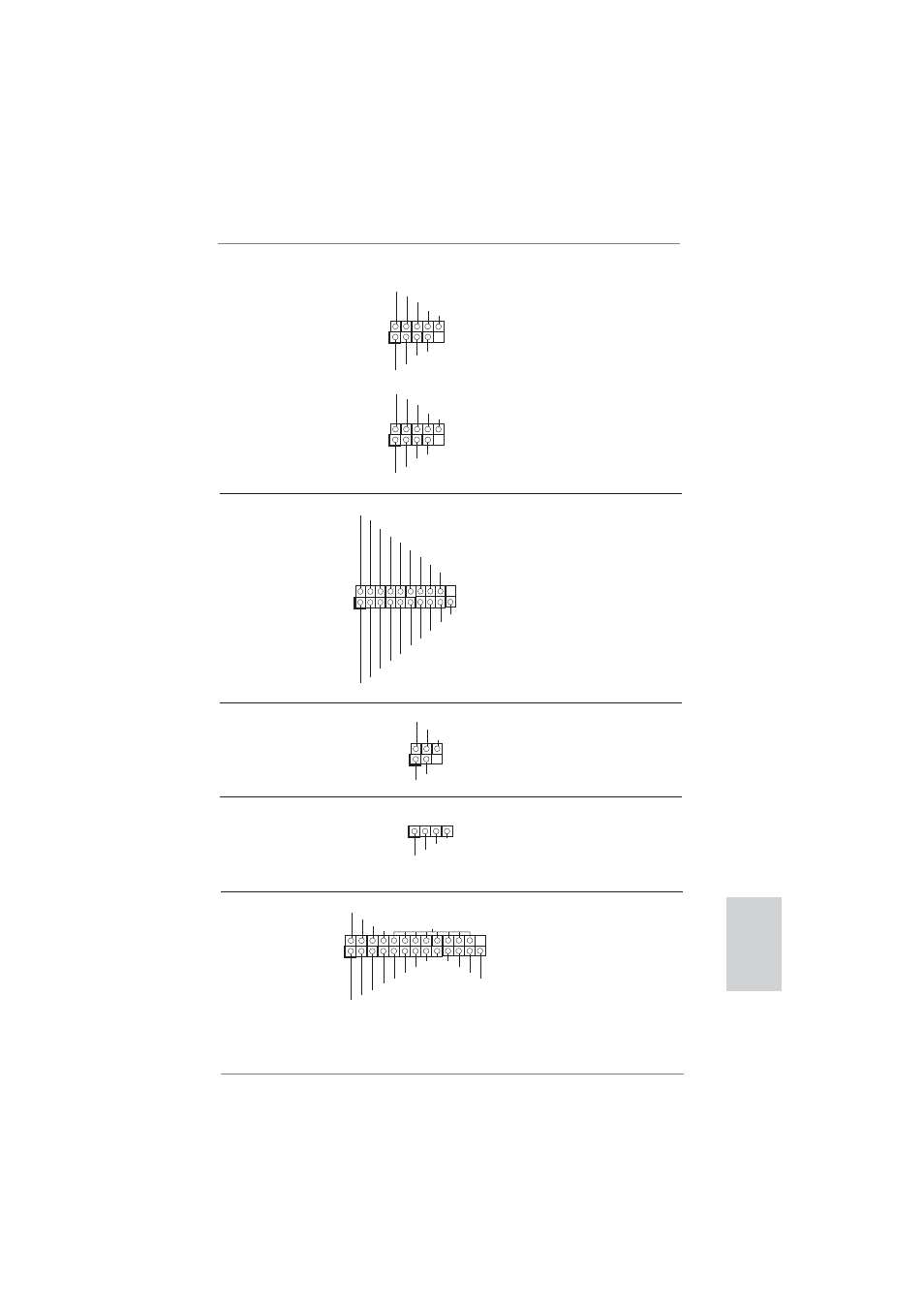
(9-pin USB8_9)
(see p.2 No. 21)
(9-pin USB10_11)
(see p.2 No. 22)
1
USB_PWR
P-8
GND
DUMMY
USB_PWR
P+8
GND
P-9
P+9
1
USB_PWR
P-10
GND
DUMMY
USB_PWR
P+10
GND
P-11
P+11
Print Port Header
This is an interface for print
(25-pin LPT1)
port cable that allows
(see p.2 No. 26)
convenient connection of printer
devices.
Infrared Module Header
This header supports an
(5-pin IR1)
optional wireless transmitting
(see p.2 No. 25)
and receiving infrared module.
1
IRTX
+5VSB
DUMMY
IRRX
GND
Consumer Infrared Module Header
This header can be used to
(4-pin CIR1)
connect the remote
(see p.2 No. 24)
controller
receiver.
1
ATX+5VSB
IRTX
GND
IRRX
1
AFD#
ERROR#
PINIT#
GND
SLIN#
STB#
SPD0
SPD1
SPD2
SPD3
SPD4
SPD5
SPD6
SPD7
ACK#
BUSY
PE
SLCT
USB 3.0 Header
Besides two default USB 3.0
(19-pin USB_12_13)
ports on the I/O panel, there is
(see p.2 No. 19)
one USB 3.0 header on this
motherboard. This USB 3.0
header can support two USB
3.0
ports.
1
ID
IntA_P1_D+
IntA_P1_D-
GND
IntA_P1_SSTX+
IntA_P1_SSTX-
GND
IntA_P1_SSRX+
IntA_P1_SSRX-
Vbus
IntA_P2_D+
IntA_P2_D-
GND
IntA_P2_SSTX+
IntA_P2_SSTX-
GND
IntA_P2_SSRX+
IntA_P2_SSRX-
Vbus