Accusys ACS-75130 User Manual
Page 12
English - 12
3. Insert the 7500 Controller Box into the space of two
half-height 5 ¼” drive bays, and secure it in place with the
screws provided. (If your case uses guide rails to install 5
¼ ” devices, you can use them on the Controller Box.)
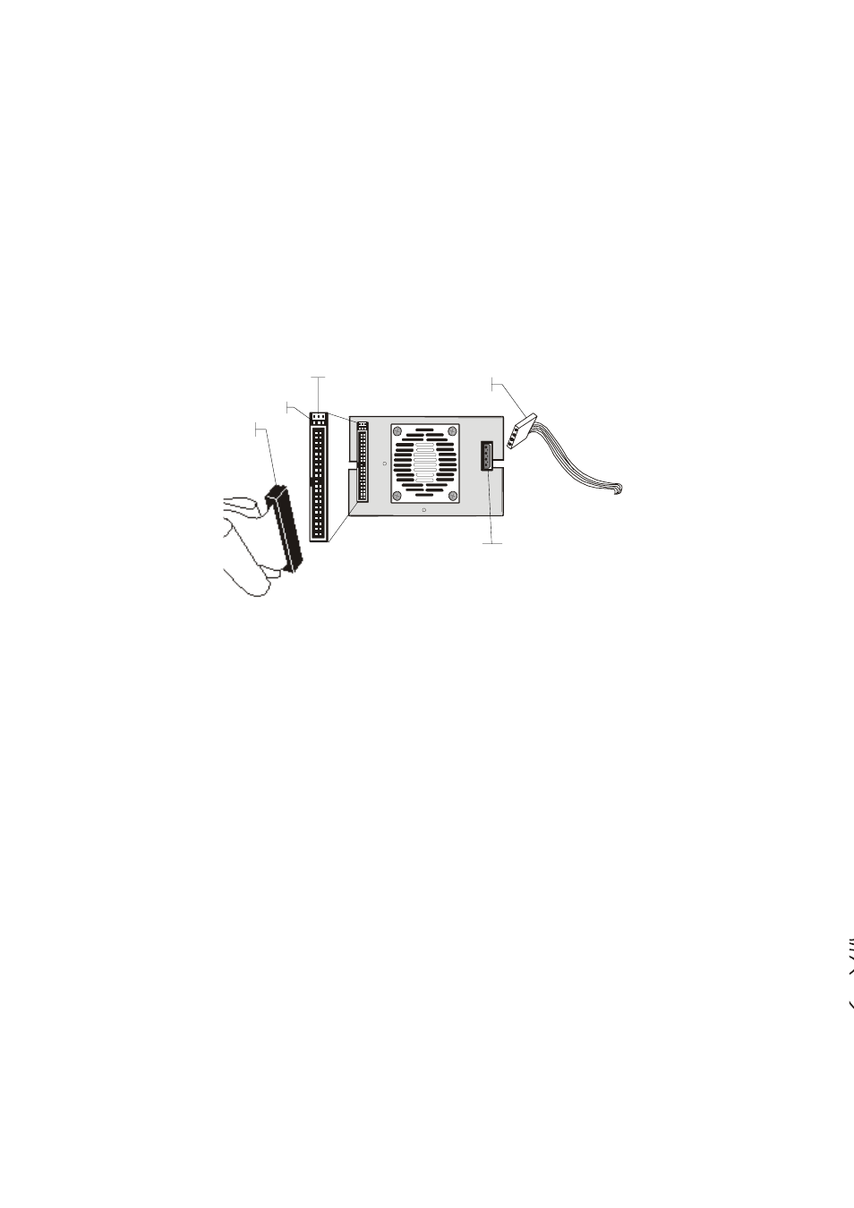
Power Cable
Power Socket
IDE Socket
Pin 1
IDE Cable
4. Connect a free power cable to the power connector on the
rear side of the Controller Box.
5. Connect an IDE 80-pin ribbon cable connector to the IDE
connector on the rear side of the Controller Box. Make
sure the red stripe on the ribbon cable is aligned with pin 1
of the IDE connector.
NOTE: According to ATAPI specifications, please do not
use an IDE 80-pin ribbon cable longer than 46 cm
(18”).
6. Reassemble your computer.