3 system layout – Muratec F-116 User Manual
Page 24
Product specification and feature
2-12
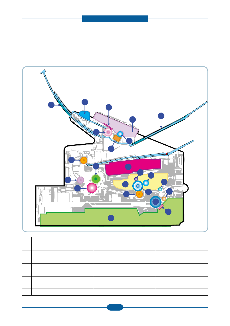
2.2.3 System Layout
This model is consisted of the Engine parts and F/W, and said engine parts is consisted of the mechanical
parts comprising Frame, Feeding, Developing, Driving, Transferring, Fusing, Cabinet and H/W comprising
the main control board, power board, operation panel, PC Interface.
20
2
17
21
22
16
23
1
15
14
12
11
3
4
10
13
18
9
5
6
7
8
19
1 Top out-bin delivery roller
9 Separation Pad
17 ADF rubber
2 Fusing roller
10 Pick up roller
18 White roller
3 LSU
11 Transfer roller
19 CIS
4 Toner Cartridge
12 OPC
20 Guide DOC
5 Primary charging roller
13 Cassette
21 OPE
6 Developer roller
14 Pressure roller
22 Tray ADF output
7 Registration/
Multipurpose pick up roller
15 Fuser Exit roller
23 Tray ADF input
8 Feed roller
16 ADF roller
This manual is related to the following products: