Figure 8 - unit dimensions, Table 6: unit height, Table 7: unit clearances – York DM150 User Manual
Page 12: Detail b, Detail c, Detail d
127408-YIM-B-0606
12
Unitary Products Group
NOTE:
A one-inch clearance must be provided between
any combustible material and the supply ductwork
for a distance of 3 feet from the unit.
NOTE:
If the unit includes gas heating, locate the unit so
the flue exhaust is at least:
•
Three (3) feet above any forced air inlet located within 10
horizontal feet (excluding those integral to the unit).
•
Four (4) feet below, four (4) horizontal feet from, or one
(1) foot above any door or gravity air inlet into the build-
ing.
•
Four (4) feet from electric meters, gas meters, regula-
tors, and relief equipment.
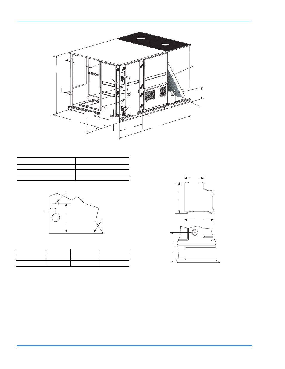
FIGURE 8 -
UNIT DIMENSIONS
6HH'HWDLO
%
)RU%DVHUDLO
'LPHQVLRQV
6HH'HWDLO&
3RZHU
(QWU\
&RQWURO
(QWU\
3RZHU
(QWU\
/()7
)5217
&RQYHQLHQFH
3RZHU
2XWOHW
(QWU\
127([[[LQGLFDWHVGLPHQVLRQV
JLYHQLQPLOOLPHWHUV
)RU'UDLQ
'LPHQVLRQV
6HH'HWDLO'
8
TABLE 6: UNIT HEIGHT
Unit Model Number
X
DM090
42 (1067)
DM120
50 3/4 (1289)
DM150
50 3/4 (1289)
TABLE 7: UNIT CLEARANCES
*
*.
In inches and millimeters, in.(mm).
Top
†
†.
Units must be installed outdoors. Overhanging struc-
ture or shrubs should not obstruct condenser air dis-
charge outlet.
72(1830)
Right
12(305)
Front
36(915)
Left
36(915)
Rear
‡
‡.
To remove the slide-out drain pan, a rear clearance of
60” (1525 mm) is required. If space is unavailable, the
drain pan can be removed through the front by separat-
ing the corner wall.
36(915)
Bottom
**
**.
Units may be installed on combustible floors.
0(0)
5 - 1 / 4
( 1 3 5 )
B a s e
P a n
1 7 - 1 3 / 1 6
( 4 5 0 )
V i e w o f W a l l A c r o s s f r o m C o i l
G a s P i p e I n l e t
DETAIL B
3 - 3 / 4
( 9 5 )
3 - 9 / 1 6
( 9 0 )
2 - 3 / 8
( 6 0 )
DETAIL C
5 - 3 / 8
( 1 3 5 )
DETAIL D