York STELLAR PLUS E*FH060 User Manual
Page 2
036-21031-004 Rev. A (0603)
2
Unitary Products Group
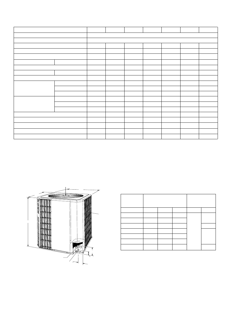
All dimensions are in inches. They are subject to change
without notice. Certified dimensions will be provided upon
request.
PHYSICAL AND ELECTRICAL DATA
MODEL
E4FH018
E4FH024
E4FH030
E4FH036
E4FH045
E5FH048
E4FH060
Unit Supply Voltage
208/230-1-60
Normal Voltage Range
1
1. Rated in accordance with ARI Standard 110, utilization range “A”.
187 to 252
Minimum Circuit Ampacity
9.7
16.2
16.4
22.1
25.4
33.3
37.8
Max. Overcurrent Device Amps
2
2. Dual element fuses or HACR circuit breaker.
15
25
25
35
35
50
50
Compressor Type
3
3. All scrolls listed with a superscript “B” are Bristol scrolls. All scrolls listed with a superscript “C” are Copeland scrolls.
Recip
Scroll
C
Scroll
C
Scroll
C
Scroll
C
Scroll
C
Scroll
C
Compressor Amps
Rated Load
6.7
10.3
12.2
16.4
19
21.4
28.8
Crankcase Heater
Yes
No
No
No
No
No
No
Fan Motor Amps
Rated Load
0.8
0.8
0.9
1.6
1.6
1.6
1.8
Fan Diameter Inches
18
18
18
24
24
24
24
Fan Motor
Rated HP
1/12
1/12
1/8
1/4
1/4
1/4
1/3
Nominal RPM
1050
1050
1075
850
850
850
1075
Nominal CFM
1500
1500
2050
3300
3400
3400
4100
Coil
Face Area Sq. Ft.
14.1
14.1
14.1
20.0
24
24
24
Rows Deep
1
1
1
1
1
1
2
Fin / Inches
16
16
20
16
16
16
13
Liquid Line OD
3/8
3/8
3/8
3/8
3/8
3/8
3/8
Vapor Line OD
5/8
5/8
3/4
7/8
7/8
7/8
1 - 1/8
Unit Charge (Lbs. - Oz.)
4
4. The Unit Charge is correct for the outdoor unit, matched indoor coil and 15 feet of refrigerant tubing. For tubing lengths other than 15 feet, add or sub-
tract the amount of refrigerant, using the difference in length multiplied by the per foot value.
5 - 9
5 - 1
5 - 9
6 - 14
8 - 3
9 - 11
14 - 0
Charge Per Foot, Oz.
0.68
0.68
0.68
0 .68
0 .70
0.70
0.70
Operating Weight Lbs.
156
148
150
212
237
272
300
48" OVERHEAD
CLEARANCE
C
B
A
5-1/2
2-3/8
3-1/8
VAPOR
CONNECTION
LIQUID CONNECTION
AIR IN
4 SIDES
UNIT MODEL
EFH
DIMENSIONS
REFRIGERANT
CONNECTION
LINE SIZE
A
B
C
LIQUID
VAPOR
018
30-1/8
24
24
3/8
5/8
024
30-1/8
24
24
030
30-1/8
24
24
3/4
036
30-7/8
35
35
7/8
042
37-7/8
35
35
048
37-7/8
35
35
060
37-7/8
35
35
1-1/8
1
1. Valve on 060 is 7/8 with a reducer supplied for the 1-1/8
vapor line.