Weil-McLain GOLD CGs User Manual
Page 13
V
V
V
V
Vertical Direct V
ertical Direct V
ertical Direct V
ertical Direct V
ertical Direct Venting — V
enting — V
enting — V
enting — V
enting — Venting Supplement
enting Supplement
enting Supplement
enting Supplement
enting Supplement
Part Number 550-141-873/0502
13
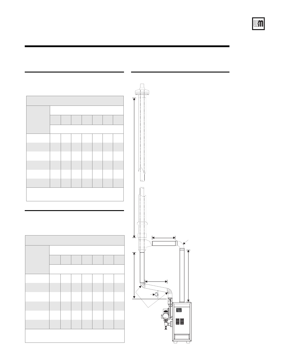
Figure 11
Typical vent/air piping
Table 4
CGs-3 and CGs-4
Maximum connector pipe length, vent or air:
•
Combustion air connector pipe
•
Vent connector pipe
87304
D
L
L
= B
-vent length
A
B
C
Elbow
Elbows
V
ent piping
Combustion air piping
A + B
C + D
= Combustion air
connector piping length
= Vent connector piping length
Condensate
drain line
CGs-3 and CGs-4
“B-Vent”
length
(feet)
L
Total number of elbows
1
2
3
4
5
6
7
Max. length from boiler to “B-Vent”
5
50
43
36
29
22
15
8
10
45
38
31
24
17
10
3
15
40
33
26
19
12
5
--
20
35
28
21
14
7
--
--
25
30
23
16
9
2
--
--
30
25
18
11
4
--
--
--
Note: Combustion air connector pipe length = A + B
Vent connector pipe length = C + D
CGs-5 and CGs-6
“B-Vent”
length
(feet)
L
Total number of elbows
1
2
3
4
5
6
7
Max. length from boiler to “B-Vent”
5
40
33
26
19
12
5
--
10
35
28
21
14
7
--
--
15
30
23
16
9
2
--
--
20
25
18
11
4
--
--
--
25
20
13
6
--
--
--
--
30
15
8
1
--
--
--
--
Note: Combustion air connector pipe length = A + B
Vent connector pipe length = C + D
Table 5
CGs-5 and CGs-6
Maximum connector pipe length, vent or air:
•
Combustion air connector pipe
•
Vent connector pipe