Multiple modulating boilers, Direct heating piping diagram, Bmc and bmc-6x installation and operation manual – Weil-McLain BMC-6X User Manual
Page 29: System, Ma gnd vlt, Ma temp outdoor o o temp system extension module, Prove /dhw shutdown /setback
29
BMC and BMC-6X Installation and Operation Manual
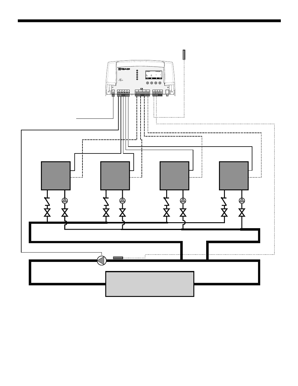
MULTIPLE MODULATING BOILERS
DIRECT HEATING PIPING DIAGRAM
Outdoor
Sensor
System
Sensor
120VAC
Boiler 1
Boiler 2
Boiler 3
Boiler 4
Building Heating Loop
BMC
SYSTEM
A
B
C
D
Full Modulation Sequencing Control
1
2
RUN
PROGRAM
DO NOT APPLY ANY VOLTAGE
TO INPUT TERMINALS
3
4
5
6
7
8
9 10 11 12
13
15
14
17
16
18
22
20
19
21
24
23
29
25
27
26
28
32
30 31
L N
-
+
+
T
T
O
O
RS-485
mA
GND
VLT
SYS
A
B
C
D
PWR
CUR / VLT
A
-
+
+
mA
GND
VLT
-
+
+
mA
GND
VLT
-
+
+
mA
GND
VLT
+
mA
TEMP
OUTDOOR
O
O
TEMP
SYSTEM
EXTENSION
MODULE
CUR / VLT
B
CUR / VLT
C
CUR / VLT
D
---
---
PROVE
/DHW
SHUTDOWN
/SETBACK
FOR ALL CIRCUITS
120VAC, 6A RESISTIVE
OUTPUT RATINGS:
1A PILOT DUTY, 15A TOTAL
115VAC 60Hz , 30VA MAX
INPUT RATINGS:
USE COPPER WIRE,
CLASS 1 WIRE ONLY.
ENCLOSED
ENERGY
MANAGEMENT
EQUIPMENT
LISTED
99RA
CAUTION: RISK OF ELECTRIC SHOCK
More than one disconnect switch may be required
to de-energize the equipment before servicing.
System:
The BMC provides 4 modulating boilers. The boilers are piped in Reverse Return on the primary loop. The System
output is controlling the System Pump.
Weil McLain is aware that each installation is unique. Thus, Weil McLain is not responsible for any installation related to
any electrical or plumbing diagram generated by Weil McLain. The provided illustrations are to demonstrate Weil McLain’s
control operating concept only.