Bmc and bmc-6x installation and operation manual, Connecting bmc to two extension panels using rs485, Wiring to modulating motors – Weil-McLain BMC-6X User Manual
Page 11: Connecting to the bmc-6x panels, Bmc-6x a, Bmc-6x b
11
BMC and BMC-6X Installation and Operation Manual
WIRING TO MODULATING MOTORS
The BMC can modulate any combination of the following motors. The Output Type must be selected properly
before connecting any output wires to avoid damage components. See Output Type on page 11.
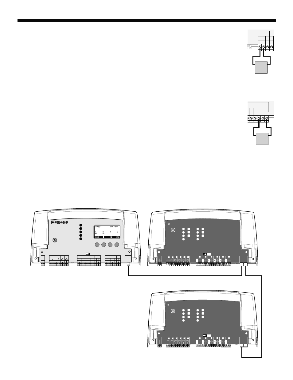
WIRING THE 4-20MA MODULATING MOTORS (A TERMINALS 13, 14), (B TERMINALS 16, 17),...
•
The BMC can operate up to four 4-20 mA modulating motors.
•
The BMC-6X can operate up to six 4-20 mA modulating motors.
•
The BMC and the BMC-6X sources 24VDC excitation voltage for the 4-20mA signal.
•
Wire the (-) from the modulating motor to the boiler terminal on the BMC marked (GND). That is for boiler A,
the modulating (-) terminal will be 13.
•
Wire the (+) from the modulating motor to the boiler terminal on the BMC marked (mA). That is for boiler A,
the modulating (-) terminal will be 14.
13
15
14
1
16
-
+
+
mA
GND
VLT
CUR / VLT
A
-
GND
CUR
Boiler 4-20mA
Modulation Output
4-20mA
Burner
Motor
-
+
WIRING THE VOLTAGE MODULATING MOTORS (A TERMINALS 13, 15), (B TERMINALS 16, 18),...
•
The BMC can operate up to four 0-5V, 0-10V, 1-5V, or 2-10V modulating motors.
•
The BMC-6X can operate up to six 0-5V, 0-10V, 1-5V, or 2-10V modulating motors.
•
Wire the (GND) from the modulating motor to the boiler terminal on the BMC marked (GND). That is for
boiler D, the modulating (GND) terminal will be 22.
•
Wire the (V+) from the modulating motor to the boiler terminal on the BMC marked (VLT+). That is for
boiler D, the modulating (V+) terminal will be 23.
22
20
9
21
24
23
+
+
mA
D
VLT
-
+
+
mA
GND
VLT
+
mA
UR / VLT
C
CUR / VLT
D
Boiler Voltage
Modulation Output
Voltage
Burner
Motor
GND
V+
CONNECTING TO THE BMC-6X PANELS
•
The BMC is equipped with a 6-pin phone socket (RS485) to connect to extension panels. The BMC-6X is equipped with two
6-pin phone sockets to connect to BMC and an additional BMC-6X.
•
Configure the Output Types (see page 11) after connecting the Extension panels to be able to configure their outputs.
•
Only 6-wire phone cable must be used for proper operation.
•
Connection cable is provided as part of the BMC-6X package.
•
Phone cables must be of a 6-wire with 6-pin terminals. Phone cables can extend up to 100'.
Full Modulation Sequencing Extension
F
H
J
Power
CAUTION:
Risk of Electric Shock.
More than one disconnect switch may be required
to de-energize the equipment before servicing.
PWR
L N
1 2
E
3 4
F
5 6
G
7 8
H
9 10
I
11 12
EXTENSION
MODULE
RS-485
Ext A
INPUT RATINGS:
115VAC 60Hz, 12VA MAX
Use Copper Conductors Only.
OUTPUT RATINGS:
120VAC, 6A RESISTIVE
1A PILOT DUTY, 15A TOTAL
FOR ALL CIRCUITS
ENCLOSED
ENERGY
MANAGEMENT
EQUIPMENT
LISTED
99RA
E
G
I
Comm
Ext B
K
M
O
L
N
P
15
14
VLT
mA
CUR / VLT
18
17
16
VLT
mA
GND
CUR / VLT
21
20
19
VLT
mA
GND
CUR / VLT
24
23
22
VLT
mA
GND
CUR / VLT
J
11 12
K
M
O
L
N
P
E
F
G
H
K
M
L
N
13
GND
16
GND
19
GND
22
GND
27
26
VLT
mA
CUR / VLT
30
29
16
VLT
mA
GND
CUR / VLT
25
GND
28
GND
I
J
O
P
BMC-6X A
BMC-6X
Full Modulation Sequencing Extension
F
H
J
Power
CAUTION:
Risk of Electric Shock.
More than one disconnect switch may be required
to de-energize the equipment before servicing.
PWR
L N
1 2
E
3 4
F
5 6
G
7 8
H
9 10
I
11 12
EXTENSION
MODULE
RS-485
Ext A
INPUT RATINGS:
115VAC 60Hz, 12VA MAX
Use Copper Conductors Only.
OUTPUT RATINGS:
120VAC, 6A RESISTIVE
1A PILOT DUTY, 15A TOTAL
FOR ALL CIRCUITS
ENCLOSED
ENERGY
MANAGEMENT
EQUIPMENT
LISTED
99RA
E
G
I
Comm
Ext B
K
M
O
L
N
P
15
14
VLT
mA
CUR / VLT
18
17
16
VLT
mA
GND
CUR / VLT
21
20
19
VLT
mA
GND
CUR / VLT
24
23
22
VLT
mA
GND
CUR / VLT
J
11 12
K
M
O
L
N
P
E
F
G
H
K
M
L
N
13
GND
16
GND
19
GND
22
GND
27
26
VLT
mA
CUR / VLT
30
29
16
VLT
mA
GND
CUR / VLT
25
GND
28
GND
I
J
O
P
BMC-6X B
Connecting BMC to
Two Extension Panels
using RS485
BMC
BMC
SYSTEM
A
B
C
D
Full Modulation Sequencing Control
1
2
RUN
PROGRAM
DO NOT APPLY ANY VOLTAGE
TO INPUT TERMINALS
3
4
5
6
7
8
9 10 11 12
13
15
14
17
16
18
22
20
19
21
24
23
29
25
27
26
28
32
30 31
L N
-
+
+
T
T
O
O
RS-485
mA
GND
VLT
SYS
A
B
C
D
PWR
CUR / VLT
A
-
+
+
mA
GND
VLT
-
+
+
mA
GND
VLT
-
+
+
mA
GND
VLT
+
mA
TEMP
OUTDOOR
O
O
TEMP
SYSTEM
EXTENSION
MODULE
CUR / VLT
B
CUR / VLT
C
CUR / VLT
D
---
---
PROVE
/DHW
SHUTDOWN
/SETBACK
FOR ALL CIRCUITS
120VAC, 6A RESISTIVE
OUTPUT RATINGS:
1A PILOT DUTY, 15A TOTAL
115VAC 60Hz , 30VA MAX
INPUT RATINGS:
USE COPPER WIRE,
CLASS 1 WIRE ONLY.
ENCLOSED
ENERGY
MANAGEMENT
EQUIPMENT
LISTED
99RA
CAUTION: RISK OF ELECTRIC SHOCK
More than one disconnect switch may be required
to de-energize the equipment before servicing.
BMC-6X
C
US
/TSAT
C
US
C
US