Top brackets – Wayne-Dalton 8500 User Manual
Page 8
Please Do not Return This Product To The Store. Contact your local Wayne-Dalton dealer. To find your local Wayne-Dalton dealer,
refer to your local yellow pages business listings or go to the find a Dealer section online at www.wayne-dalton.com
Vertical
track
Jamb
bracket
Flag
angle
Flag angle lag screw locations
5/16” x 1-5/8”
Lag screws
Bottom
section
12R FA
3/8” to 5/8”
Spacing
Bottom section
Vertical track
15R FA
15R QI
12R QI
stacking sections/ securing jambs
12
Tools: Power drill,7/16” Socket driver
NOTE: Refer to door section identification.
NOTE: Make sure hinges are flipped down, when stacking another section on top.
Place rollers into end hinges of remaining sections.
With assistance, lift second section and guide rollers into the vertical tracks. Lower section
until it is seated against bottom section. flip hinges up. fasten intermediate hinge(s) first
using (2) 1/4”-14 x 7/8” self drilling screws, then end hinges, using (3) 1/4”-14 x 7/8” self
drilling screws. Repeat for other sections, except top section.
IMPORTANT: PuSH & HOLD THE HInGE LEAfS SECuRELY AGAInST THE SECTIOnS WHILE
SecURing WiTH 1/4”-14 x 7/8” SeLf DRiLLing ScReWS. THeRe SHoULD Be no gAP
BETWEEn THE HInGE LEAfS AnD THE SECTIOnS.
Remaining jB-uS jamb brackets will be installed at this time.
NOTE: for instructions on attaching jB-uS jamb brackets to vertical tracks and jambs, see
steps Attaching jB-uS jamb brackets and Vertical Tracks.
Attach JB-US jamb brackets to vertical tracks at the following locations: The middle of each
section, all end-hinge/ roller locations, and even with bottom brackets. Attach all jamb
brackets to jambs.
If the two jB-uS jamb brackets which were previously attached to the vertical track in step,
Attaching jB-uS jamb brackets, are not even with the middle of a section or an end-hinge/
roller location, unfasten them from their current location and move them to a proper location
along the middle of a section or an end-hinge/ roller location.
NOTE: for windload option codes 0124 and 0132, a hole will need to be drilled in the vertical
track to install an additional jB-uS jamb bracket.
Drill a 9/32” diameter hole through the outside leg of the vertical track, inline with the other
jB-uS holes, at the height of the highest end hinge location. Attach jB-uS jamb bracket to
vertical track as shown in step, Attaching jB-uS jamb brackets. Attach jamb bracket to jamb.
Ensure all jamb brackets are secured tightly to the vertical tracks and jambs.
NOTE: Install lock at this time (sold separately). See optional installation step, Side Lock.
Lock section
Vertical
tracks
Intermediate
hinge(s)
Left
end hinge
Right
end hinge
1/4”-14 x 7/8” Self drilling screw locations
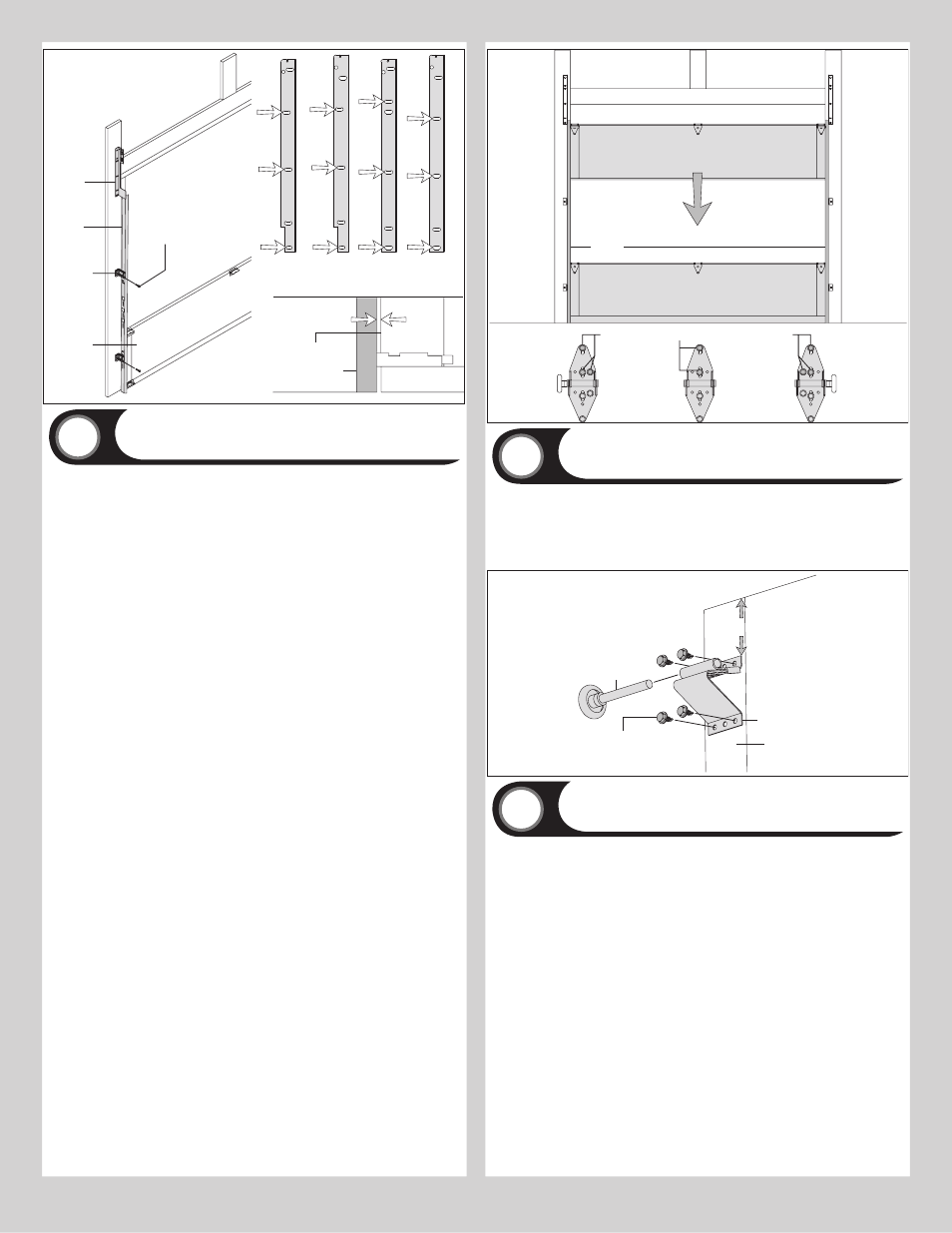
Top Brackets
13
Tools: Power drill, 7/16” Socket driver, Tape measure
Align the top bracket assembly 3” down from the top section and even with the edge of the
section, the slotted half of the bracket base should be facing upwards. fasten to section
through end cap using (4) 1/4”-14 x 7/8” self drilling screws. The bracket will be tightened
and adjusted later, in step, Adjusting Top Brackets. Insert roller into top bracket slide. Repeat
for other side.
Top section
(4) 1/4”-20 x 5/8”
Self drilling screws
Top bracket assembly
3”
Roller
End cap
Top section
14
Tools: Hammer, Step ladder, Tape measure
Place the top section in the opening. Temporarily secure the top section by driving a nail
in the header near the center of the door and bending it over the top section. now, flip up
the hinge leaves, hold tight against section, and fasten center hinges first and end hinges
last (refer to step, Stacking Sections). Vertical track alignment is critical. Position flag angle
between 1-11/16” (43 mm) to 1-3/4” (44 mm) from the edge of the door; tighten the bottom
lag screw. flag angles must be parallel to the door sections. Repeat for other side.
IMPORTANT: THE DIMEnSIOn BETWEEn THE fLAG AnGLES MuST BE DOOR WIDTH PLuS
3-3/8” (86MM) To 3-1/2” (89 MM) foR SMooTH, SAfe DooR oPeRATion.
Complete the vertical track installation by securing the jamb bracket(s) and tightening the
other lag screws. Push the vertical track against the rollers so that the rollers are touching
the deepest part of the curved side of the track as shown; tighten all the track bolts and nuts.
Repeat for other side.
8