Warning, Installation, Attaching q.i. flag angles to vertical tracks – Wayne-Dalton 8500 User Manual
Page 5: Attaching f.a. flag angles to vertical tracks, Attaching jb-us jamb brackets, Horizontal angles, Bottom brackets and counterbalance
InsTallaTIon
Before installing your door, be certain that you have read and followed all of the instruc-
tions covered in the pre-installation section of this manual. failure to do so may result in an
improperly installed door.
Attaching Q.I. flag Angles to vertical Tracks
1
Tools: None
NOTE: If you have f.A. flag angles, skip this step.
NOTE: flag angles are right and left handed.
Place the lower q.I. tab of the left hand flag angle in the q.I. feature of the left hand vertical
track. Give the flag angle 1/4 turn to lock in place. Repeat for other side.
1/4 Turn
Flag angle
Vertical
track
Lower
Q.I. tab
Q.I.
feature
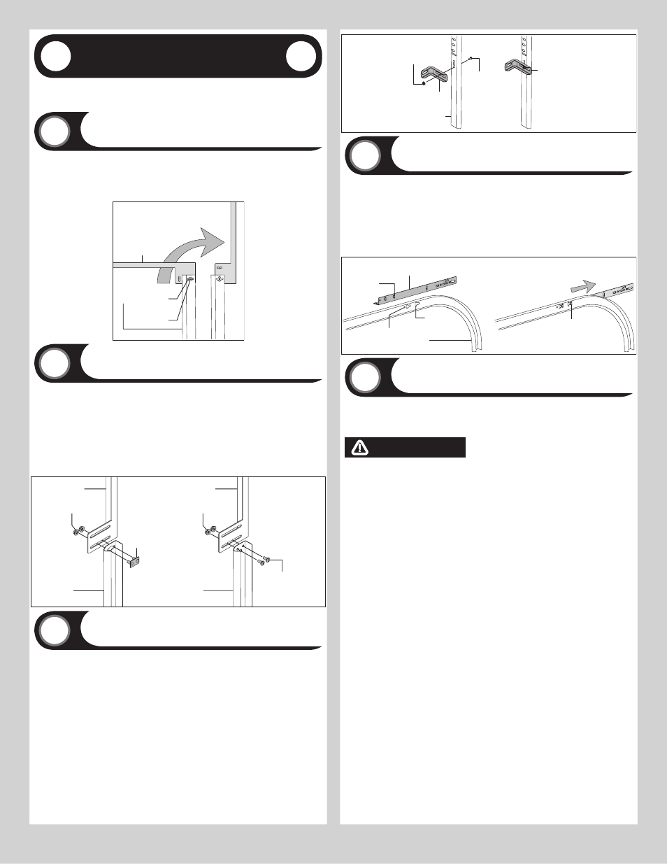
Attaching f.A. flag Angles to vertical Tracks
2
Tools: None
NOTE: If you have q.I. flag angles, skip this step.
NOTE: flag angles are right and left handed.
for Q.I. vertical tracks: Hand tighten the left hand flag angle to the left hand vertical track
using (1) stud plate and (2) 1/4” – 20 flange hex nuts. Repeat for the other side.
for f.A. vertical tracks: Hand tighten the left hand flag angle to the left hand vertical track
using (2) 1/4”-20 x 9/16” track bolts and (2) 1/4”-20 flange hex nuts. Repeat for other side.
flange nuts will be secured after flag angle spacing is completed in step, Top Section.
Q.I.vertical
track
Stud
plate
Flag angle
1/4”-20
Flange hex nuts
1/4”- 20 x 9/16”
Track bolts
Flag angle
F.A. vertical
track
1/4”-20
Flange hex nuts
Attaching jB-us jamb Brackets
3
Tools: None
Two jB-uS jamb brackets will be attached to the vertical track at this time. The remaining
jamb brackets will be attached after the sections are stacked so that their position can more
easily be determined.
The position of the two JB-US jamb brackets to be installed at this time should be as follows:
One jamb bracket will be installed at the bottom hole/ slot pattern of the vertical track;
another jamb bracket will be installed at the approximate center location of the vertical track.
Align the slot in the jamb brackets with the hole of the hole/ slot patterns. Secure jamb
brackets using (1) 1/4”-20 x 9/16” track bolt and (1) 1/4”-20 flange hex nut. Repeat for
other side.
JB-US jamb
bracket
Vertical track
1/4”- 20 x
9/16”
Track bolt
1/4”- 20
Flange hex nut
Jamb bracket
in place
horizontal Angles
4
Tools: Hammer
NOTE: for larger doors, a full length horizontal angle may not already be spot welded to the
horizontal track. If the horizontal angle is not welded, the horizontal angle will be installed as
shown.
Position the left hand horizontal angle as shown. Place the q.I. tabs of the horizontal angle
in the key slot of the left hand horizontal track. using a hammer, tap the horizontal angle to-
wards the curved end of the track until the alignment hole in the track and angle are aligned.
Repeat for other side. Set tracks aside.
Horizontal
angle
Key slots
Horizontal
track
Alignment
hole
Q.I. tabs
Q.I. tabs
in place
Bottom Brackets and Counterbalance
5
Tools: Power drill, 7/16” Socket driver, 1/4” Torx bit
NOTE: Refer to door section identification, located in the pre-installation section of this
manual.
NOTE: Cable drums and bottom brackets are marked right and left hand.
WARNING
WARNING
fAILuRE TO ENsuRE TIGhT fIT Of CABLE LOOP OvER MILfORD PIN COuLD
REsuLT IN CABLE COMING Off ThE PIN, ALLOWING ThE DOOR TO fALL,
POssIBLy REsuLTING IN sEvERE OR fATAL INjuRy.
for doors with bottom brackets shown in top illustration: Attach left hand bottom
bracket to the left corner of the bottom section, making sure it is seated to the edges of the
end cap, with (2) 1/4”-14 x 7/8” self drilling screws and (1) 1/4”-14 x 5/8” tamper resistant
self drilling screw.
uncoil the counterbalance cables from the drums, making sure you place the left hand cable
loop on the left hand milford pin of the bottom bracket.
NOTE: Check to ensure cable loop fits tightly over the milford pin.
Insert a roller into spacer and the bottom bracket.
Repeat for other side.
NOTE: Verify astragal (bottom seal) is aligned with door section. If there is more than 1/2”
excess astragal on either side, trim astragal even with door section.
for doors with bottom brackets shown in middle illustration: Attach left hand bottom
bracket to the left corner of the bottom section, making sure it is seated to the edges of the
end cap, with (4) 1/4”-14 x 7/8” self drilling screws and (1) 1/4”-14 x 5/8” tamper resistant
self drilling screw.
uncoil the counterbalance cables from the drums, placing the left hand cable loop into
position between the two holes on the side of the left hand bottom bracket. Slide a clevis pin
through the innermost hole, cable loop, and outermost hole, of the bottom bracket. Slide a
washer onto the clevis pin and secure in place by inserting a cotter pin into the hole of the
clevis pin. Bend the ends of the cotter pin outwards to secure it in place.
Insert a roller into spacer and the bottom bracket.
Repeat for other side.
NOTE: Verify astragal (bottom seal) is aligned with door section. If there is more than 1/2”
excess astragal on either side, trim astragal even with door section.
for doors with bottom brackets shown in bottom illustration: Attach left hand bottom
bracket to the left corner of the bottom section, making sure it is seated to the edges of the
end cap, with (5) 1/4”-14 x 7/8” self drilling screws.
uncoil the counterbalance cables from the drums, making sure you place the left hand cable
loop on the left hand milford pin of the bottom bracket.
NOTE: Check to ensure cable loop fits tightly over the milford pin.
Insert a roller into spacer and the bottom bracket.
Please Do not Return This Product To The Store. Contact your local Wayne-Dalton dealer. To find your local Wayne-Dalton dealer,
refer to your local yellow pages business listings or go to the find a Dealer section online at www.wayne-dalton.com
5