Di/do diagram, Status led, The led indicates the status of the network camera – Vivotek IP7130 User Manual
Page 5
VIVOTEK - A Leading Provider of Multimedia Communication Solutions
User's Manual - 5
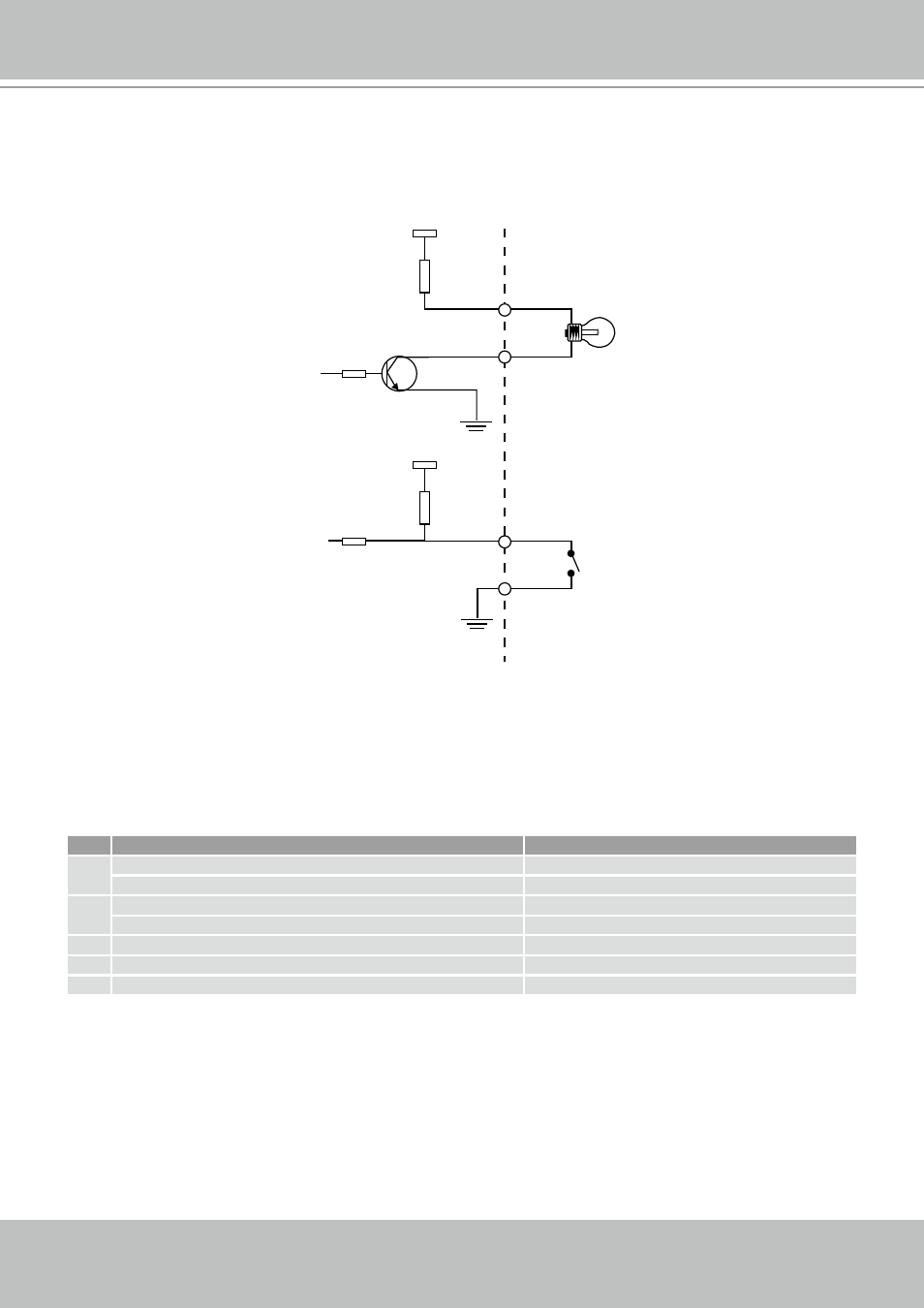
DI/DO Diagram
Please refer to the following illustration for the connection method�
12V
+12V
Digital output
PIN 1
Power+12V
PIN 2
Digital input
PIN 3
Ground
PIN 4
Status LED
The LED indicates the status of the Network Camera�
Item
LED status
Description
1 Steady Red
Power on and system booting
Red LED unlighted
Power off
2 Steady Red + Blink Green every 1 sec�
Network works (heartbeat)
Steady Red + Green LED unlighted
Network fail
3 Steady Red + Blink Green every 2 sec�
Audio mute (heartbeat)
4 Blink Red every 0�15 sec� + Blink Green every 1 sec�
Upgrading firmware
5 Blink Red every 0�15 sec� + Blink Green every 0�15 sec�
Restore default