Rear / bottom view – Vidikron Vision 30 User Manual
Page 11
11
Vidikron Vision Model 30 Owner’s Operating Manual
Overview
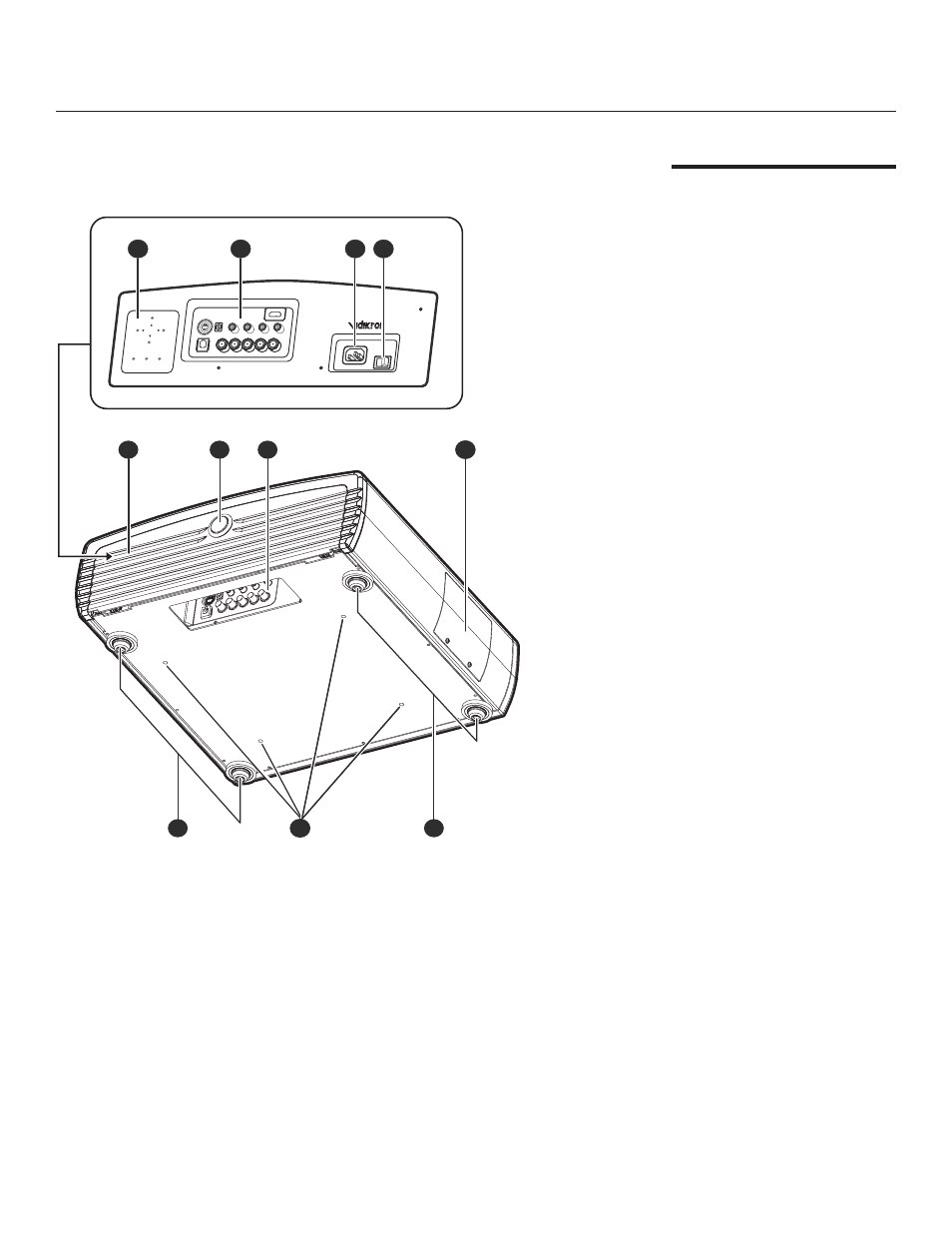
1. Built-in Control Panel
See “Built-in Control Panel” on
page 14.
2. Connector Panel
See “Connector Panel” on page 14.
3. AC Power IN Socket
4. AC Power Switch
5. Cable Access Door
Open to access connectors.
See “Connector Panel” on page 14.
6. Door Release Button
7. Cable Opening
Pass cables through this opening.
8. Lamp Module Cover
Remove this cover when replacing
the lamp. See “Lamp Replacement”
on page 47.
9. Front / Rear Adjusters
Adjusts the height or projection
angle.
10. Ceiling Mount Holes
The connecting holes for the ceiling
mount bracket.
Rear / Bottom View
MEMORY
MEMOR
Y
AUTO
AUTO
POWER
POWER
MENU
/EXIT
MENU
/EXIT
SOURCE
/ENTER
SOURCE
/ENTER
1
2
3 4
8
7
6
5
9
10
9