Trigger level (channel 0), Sample rate (channel 0), Trigger level (channel 1) – VXI TECHNOLOGY SVM2608 User Manual
Page 36: Sample rate (channel 1), Trigger level (channel 2), Sample rate (channel 2), Trigger level (channel 3), Sample rate (channel 3), Trigger level (channel 4), Trigger level (channel 5)
VXI Technology, Inc.
36
SVM2608 Programming
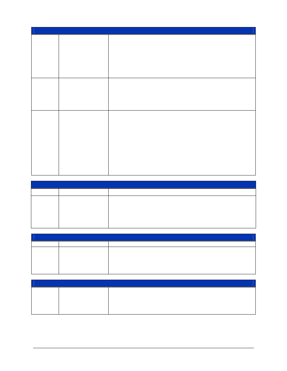
Control Register (0x08, 0x30, 0x58, 0x80, 0xA8, 0xD0) — Read & Write
D4 FILTER
20 kHz (Channels 0-3)/5 MHz (Channels 4-5) LPF Control – This bit
enables/disables the low pass frequency filter for the low-speed channels
and high-speed channels, respectively. . Before taking a measurement,
allow for at least 5 ms for internal circuits to settle after making changes.
0 = Filter off
1 = Filter on
P
on
state = 0
D3 TRGSLOPE
Input Trigger Source Slope – This bit sets the slope of the input trigger
for low-speed Channels 0 - 3.
0 = Positive
1 = Negative
P
on
state = 0
D2 – D0
TRIGSRC2 - 0
Trigger Source Control - Once the trigger is armed, the acquisition can
be triggered via software (FTRIG), any of the six channels or an external
trigger.
000 = Channel 0
001 = Channel 1
010 = Channel 2
011 = Channel 3
100 = Channel 4
101 = Channel 5
110 = External
111 = External High-Speed
Sample Rate (0x0C, 0x34, 0x5C, 0x84) — Read & Write
D15 – D9
Unused
These bits are reserved for future use.
D8 – D0
SAMPRAT24 – 16
Sample Interval – These bits set the sample rate.
Bit Weight = 100 ns/bit
Minimum Value = 100
Maximum Value = 2
24
– 1
Sample Rate (0x0E, 0x36, 0x5E, 0x86) — Read & Write
D15 – D0
SAMPRAT15 – 0
Sample Interval – These bits set the sample rate.
Bit Weight = 100 ns/bit
Minimum Value = 100
Maximum Value = 2
24
– 1
Trigger Level (0x0A, 0x32, 0x5A, 0x82, 0xAA, 0xD2) — Read & Write
D15 – D12
Unused
This is reserved for future use.
D11 – D0
TRGLVL
Trigger Level Threshold Setting – These bits set the trigger threshold
(12-bit value).
0x800 = 0 V
0x000 = -ve full scale
0xFFF = +ve full scale