Univex 5100-02-IT User Manual
Page 44
Model 5100-02-IT Combustible Gas Sensor Module
Page: 42
8.6
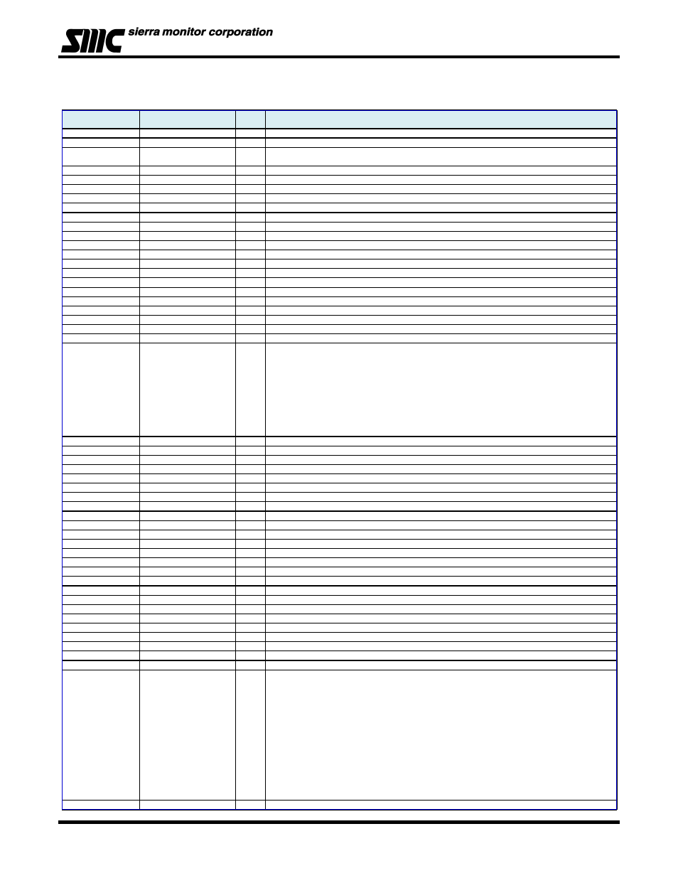
APPENDIX F: MODBUS MEMORY MAP
Table 8 - 1: Modbus Memory Map
Register
Description
Read/
Comments
Write
40001
Concentration
R
Gas concentration multiplied by Gas Scale (e.g. 209 = 20.9%)
40002
Temperature
R
Temperature in degrees Celcius scaled by a factor of 10
40003
Alarm Relay
R/W
Boolean indicating the Alarm relay status (0 = No Alarm, 1 - (High) Alarm).
Clearing bit will reset alarm.
40004
Warning Relay
R/W
Boolean indicating the Warning relay status (0 = No Alarm, 1 - Warning Alarm). Clearing bit will reset alarm.
40005
Warning Setpoint
R/W
Warning Alarm set point, used for activating Low Alarm multiplied by Gas Scale
40006
Alarm Setpoint
R/W
Alarm set point, used for activating High Alarm multiplied by Gas Scale
40007
CCC detail
R
e.g. 0001, 0007, etc
40008
Software Revision U
R
e.g. 201 denotes version 2.01
40009
Software Revision L
R
e.g. version aA is denoted by 0x6141
40010
Modbus Map Revision
R
e.g. version 2 is denoted as v2 = 0x7602
40011
Trouble Bits
R
0 = no trouble
40012
Trouble
R
1 for any trouble, 0 = no trouble
40013
Alarm Immediate
R
Like 40003, but never latched
40014
Warning Immediate
R
Like 40004, but never latched
40015
Serial Number U
R
Serial Number - 24 bits (presently set to Random ID)
40016
Serial Number L
R
40017
Run time U
R
In seconds
40018
Run time L
R
In seconds
40019
Gas (MAX) value
R
Gas concentration multiplied by Gas Scale
40020
Model
R
Read as 51028 for IR, 51002 for Cat Bead, 51005 for TOXIC H2S etc.
40021
Range
RW
40022
Units
RW
1 = %LEL, 2 = %VOL
40023
Module Status
R
A bit is defined for each of the following states:
(no bit set also means some sort of trouble)
Module State - In Calibration (0x40) = cal failed
Module State - In Calibration (0x20) = cal passed
Module State - In Calibration (0x10)
Module State - Trouble (0x08)
Module State - Warming (0x04)
Module State - RUN (ALARM) (0x02)
Module State - RUN (0x01)
40024
Gas Scale
R
Value like 1, 10 or 100
40025
Cal Concentration level
R/W
Gas concentration value used during calibration, multiplied by Gas Scale
40026
Calibration due, in days
R
Gets reset to 365 / 180 if cal successful, Less then 0 = calibration due
40027
Calibration Count
R
Counter increments if cal successful (0 = not calibrated)
40028
Display Gas Output
R
Gas value seen on display (i.e. useful during calibration)
40029
Gas (MIN) value
R
Minimum gas value multiplied by Gas Scale
40030
Alarm Time U
R
In seconds
40031
Alarm Time L
R
40032
Warning Time U
R
In seconds
40033
Warning Time L
R
40034
Trouble Time U
R
In seconds
40035
Trouble Time L
R
40036
Max Gas Time U
R
In seconds
40037
Max Gas Time L
R
40038
Min Gas Time U
R
In seconds
40039
Min Gas Time L
R
40040
Rotary Switch
R
Module address (If value < 16, the value reflects position of rotary switch)
40041
Restart Count
R
Restart count
40042
Alarm Relay Action Setup
RW
Alarm Relay Action Setup - Latch/Sentry/Non-latch
40043
Warning Relay Action Setup
RW
Warning Relay Action Setup - Latch/Sentry/Non-latch
40044
4-20mA CalibOut Value
R
40045
4-20mA TroubleOut Value
R
40046
Gas Factor
RW
Applies only to -02
40047
Force Value
RW
40048
Module Number
RW
40049
Command Register
RW
0 indicates command failed, 1 = passed, supported commands:
Lock keys = 101
Unlock keys = 102
Abort calibration = 103
Apply zero gas = 104
Apply span gas = 105
Ack alarms = 106
Reset sensor = 107
Clear mem = 108
Speed up startup = 109
Clear eeprom = 110
Force address disp= 111
Clear address disp= 112
40050
Last command executed
R
Displays last executed command from register 40049