Toshiba HWS-802XWHT6-E User Manual
Page 119
118
Toshiba
14. Display Function of Set Temperature and Other Settings
■
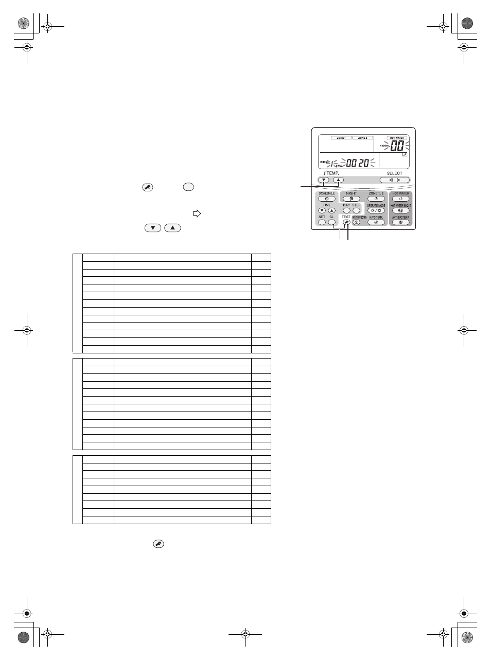
Sensor temperature display calling
This function calls the service monitor mode from the remote controller
to show the data of the remote controller, the hydro unit, and outdoor
unit.
1
Press the TEST
and CL
buttons at the same time
for 4 seconds or longer to call the service monitor mode.
The service monitor lights up, and the temperature of CODE No.
"00" displays at first.
(See display
)
2
Press the TEMP.
button for temperature setting
to change the item code to one to be monitored.
The following table shows the item codes.
3
Pressing the TEST
button returns to the usual display.
Hydr
o unit data
Item code
Data name
Unit
00
Control temperature (Hot water cylinder)
°C
01
Control temperature (Zone1)
°C
02
Control temperature (Zone2)
°C
03
Remote controller sensor temperature
°C
04
Condensed temperature (TC)
°C
06
Water inlet temperature (TWI)
°C
07
Water outlet temperature (TWO)
°C
08
Water heater outlet temperature (THO)
°C
09
Floor inlet temperature (TFI)
°C
0A
Hot water cylinder temperature (TTW)
°C
0B
Mixing valve position
step
OE
Lo pressure (Ps) × 100
MPa
O
u
tdoor
uni
t
data
Item code
Data name
Unit
60
Heat exchange temperature (TE)
°C
61
Outside air temperature (TO)
°C
62
Discharge temperature (TD)
°C
63
Suction temperature (TS)
°C
65
Heat sink temperature (THS)
°C
6A
Current
A
6D
Heat exchanger coil temperature (TL)
°C
70
Compressor operation Hz
Hz
72
Number of revolutions of outdoor fan (lower)
rpm
73
Number of revolutions of outdoor fan (upper)
rpm
74
Outdoor PMV position × 1/10
pls
S
e
rv
ic
e d
a
ta
Item code
Data name
Unit
F0
Micro computer energized accumulation time
× 100h
F1
Hot water compressor ON accumulation time
× 100h
F2
Cooling compressor ON accumulation time
× 100h
F3
Heating compressor ON accumulation time
× 100h
F4
Built-in AC pump operation accumulation time
× 100h
F5
Hot water cylinder heater operation accumulation time
× 100h
F6
Backup heater operation accumulation time
× 100h
F7
Booster heater operation accumulation time
× 100h
1 3
2
+00A09-002_01EN_SVM_ALL_Air_to_Water.book Page 118 Monday, October 5, 2009 2:09 PM