Tyan Computer Barebone System B4881V50S4H User Manual
Tyan Computer Computers
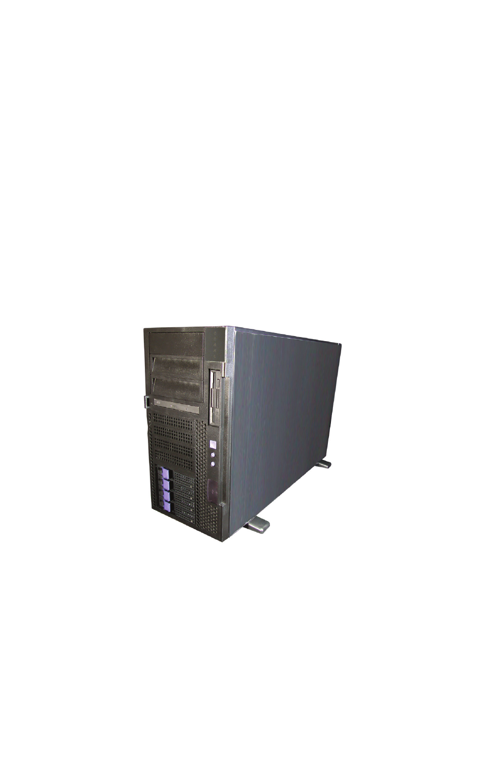
Table of contents
Document Outline
- B4881V50S4H
- User Manual
- Table of Contents
- Chapter 1: Overview
- Chapter 2: Setting up
- 2.1 Before you begin
- 2.2 Installing motherboard components
- 2.2.1 Removing the chassis cover
- 2.2.2 Installing CPUs and heatsinks
- 1. Remove the chassis cover. See Removing the chassis cover on page 13.
- 2. Remove the optional processor board if it is present, see “Replacing the CPU expansion board” on page 37
- 3. Locate the four CPU sockets on the motherboard or CPU expansion board.
- CPU sockets 1-4
- Locking lever
- Locking lever
- Heatsink retainer screws
- CPU cooling fan pin header
- 2.2.3 Installing memory
- 2.2.4 Installing CPU expansion board
- 1. Remove the chassis cover. See Removing the chassis cover on page 13.
- 2. Remove the chassis side panel as shown.
- 3. Place the HT board guides in place on the motherboard sockets.
- 4. Position the CPU expansion board in place over the motherboard. Ensure that the HT cards are located correctly above the HT card sockets on the motherboard.
- 5. Push the CPU expansion board firmly into place.
- 6. Secure in place with two screws as shown.
- 7. Insert two further coutersunk screws through the chassis to secure the expansion board to the chassis as shown.
- 8. Connect the five power cables as shown.
- 9. Replace the chassis covers.
- 2.2.5 Installing PCI-X cards
- 2.3 Installing hard drives
- 2.3.1 Installing a storage backplane
- 1. Remove the chassis cover. See Removing the chassis cover on page 13.
- 2. Remove the two screws holding the cradle locking bar in place and remove the bar.
- 3. Lift the drive housing to the vertical position.
- 4. Fix the storage backplane to the drive housing using six screws.
- 5. Press the drive housing release button and lower the drive housing back into place.
- Drive housing release button
- 2.3.2 Installing SATA/SCSI hot swap drives
- 1. Press the release clip and pull the release lever to unlock the drive tray from the chassis.
- 2. Pull the empty drive tray from the chassis.
- 3. Remove the four screws holding the plastic spacer in place in the drive tray and remove it from the tray.
- 4. Place a SATA or SCSI drive in place in the drive tray and secure with four screws.
- 5. Insert the drive tray back into the chassis and push the locking lever into place to secure it.
- 2.3.3 Installing internal hard drives
- 1. Attach a rail to each side of new hard disk. Ensure that the locking clip faces the rear of the drive. Use two screws for each rail.
- 2. Remove the chassis cover. See Removing the chassis cover on page 13.
- 3. Remove the two screws holding the cradle locking bar in place and remove the bar.
- 4. Lift the drive housing to the vertical position as shown.
- 5. Slide the new drive into place until it locks.
- 6. Press the drive housing release button and lower the drive housing back into place.
- Drive housing release button
- 2.3.1 Installing a storage backplane
- 2.4 Rack mounting
- 1. Remove the thin, center rail from each sliding rail set.
- 2. Take the remaining rails and attach the short L sections to them using the two M4L4-H2.4 screws and washers - 4.2L10-0.8.
- 3. Bolt the assembled rail sets to the rack using M5L8-H3 screws.
- 4. Remove the top, black panel from the server to reveal the rail mounting screws beneath.
- 5. Bolt one of the thin, center sliding rails to each side of the server using M4L6-H2.5 screws. Ensure that each rail is bolted on the right way round as shown.
- 6. Bolt the ears to the front of the server chassis as shown.
- 7. Lift the server up to the level of the rack and slide it between the rails mounted in the rack.
- 8. Bolt the ears to the rack using M5L15-H3 screws to secure the server in place.
- 2.5 Standalone
- 2.6 Fitting the front door assembly
- Chapter 3: Replacing pre-installed components
- 3.1 Introduction
- 3.2 Replacing motherboard components
- 3.2.1 Disconnecting all motherboard cables
- IDE socket for CD-ROM PRI-IDE, SEC-IDE
- SATA ports SATA0, SATA1, SATA2, SATA3
- Floppy disk drive port FDD
- USB pin header J30, J31, J95
- LED front panel pin header J115
- HDD LED
- Orange
- 1
- 2
- Blue
- Green SW
- 3
- 4
- Orange
- REST
- Blue
- 5
- 6
- Power on SW
- 7
- 8
- Blue
- 9
- 10
- 11
- 12
- 13
- 14
- 15
- 16
- 17
- 18
- JP4
- JP5
- LAN1
- Green
- 1
- 1
- Green
- LAN2
- Orange
- 2
- 2
- Orange
- J119
- J118
- KB-LK
- Orange
- 1
- 1
- SPAC
- Black
- 2
- 2
- Blue
- 3.2.2 Replacing the CPU expansion board
- 1. Remove the chassis cover. See Removing the chassis cover on page 13.
- 2. Remove the chassis side panel as shown.
- 3. Remove the power cables from the CPU expansion board.
- 4. Remove the two countersunk screws from the side of the chassis.
- 5. Remove the screw that secures the board to the chassis.
- 6. Lift the CPU expansion board from the chassis.
- 7. Replace the CPU expansion board as described in “Installing CPU expansion board” on page 18.
- 3.2.3 Replacing the motherboard
- 3.2.1 Disconnecting all motherboard cables
- 3.3 Replacing the slim CD-ROM drive
- 1. Remove the chassis cover. See Removing the chassis cover on page 13.
- 2. Remove the power and data cables from the CD-ROM drive.
- 3. Press the release catch that secures the CD-ROM drive and slide the CD-ROM drive from the front of the chassis.
- 4. Remove the four screws that secure the CD-ROM drive in the cradle and remove the old unit.
- 5. Remove the two screws that hold the CD-ROM backplane to the CD-ROM drive, and remove back plane.
- 6. Secure the backplane to the new CD-ROM drive with two screws.
- 7. Slide a new CD-ROM unit into the cradle and secure it with four screws.
- 8. Slide the cradle with the new CD-ROM unit back into place in the chassis. The release catch will click and secure the cradle in place.
- 9. Replace the data and power cables.
- 3.4 Replacing the floppy disk drive
- 1. Loosen the two screws that secure the lower cover to the chassis of the B4881V50S4H. Slide the cover back and remove it to expose the service port for the floppy disk drive.
- 2. Remove the power and data cables from the floppy disk drive.
- 3. Loosen the two retaining screws that secures the floppy disk drive in place.
- 4. Slide the disk drive from the chassis.
- 5. Slide the new unit into place, secure with the retaining screw and replace the power and data cables.
- 3.5 Replacing the SATA backplane
- 1. Remove the chassis cover. See Removing the chassis cover on page 13.
- 2. Remove all the SATA hot-swap HDD trays from the B4881V50S4H.
- 3. Remove all cables from the SATA backplane.
- 4. Remove the two screws holding the cradle locking bar in place and remove the bar.
- 5. Lift the disk drive cradle to the vertical position as shown. Remove the six screws and lift the backplane from the chassis.
- 6. Place a new backplane in position and secure in place with six screws.
- 7. Lower the disk drive cradle into place.
- 8. Replace the power and data cables.
- 3.6 Replacing power supplies
- 3.7 Replacing cooling fans
- 1. Remove the chassis cover. See Removing the chassis cover on page 13.
- 2. Remove the CPU expansion board as described in “Replacing the CPU expansion board” on page 37
- 3. Unplug the cooling fan power supply lead from the pin header on the mother board.
- 4. Remove the four screws that hold the fan to the chassis and remove the fan.
- 5. Place a new fan in position in the chassis and secure in place with four screws.
- 6. Plug the fan power supply into the pin header.
- Appendix