Installation and setup, Installation method – Toshiba TOSVERT VF-FS1 Series User Manual
Page 9
E6581371c
- 8 -
3. Installation and Setup
3.1. Installation
method
Install the L
ON
W
ORKS
communication option to VF-FS1 as follows.
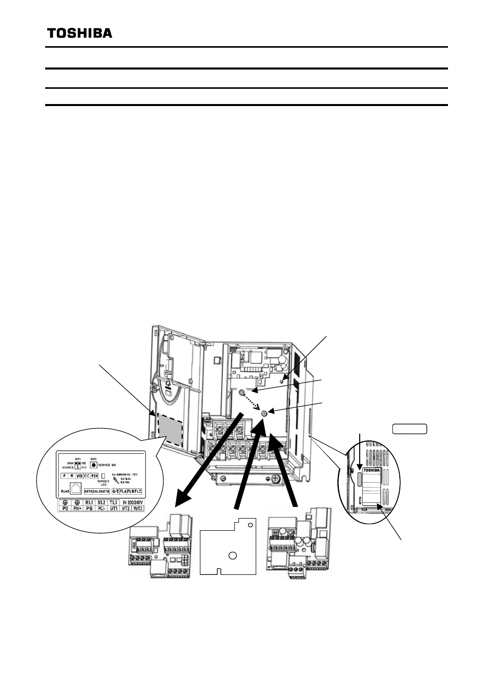
(1) Turn off the input power of VF-FS1 and wait for at least 10 minutes and then check that the
CHARGE lamp on VF-FS1 is no longer lit.
(2) Open the VF-FS1 front cover, remove the terminal board fixing screw and take off the VF-FS1
standard terminal board.
(Be careful not to lose the terminal board fixing screw when removed since it may be used again.)
(3) Perform wiring an inverter before installing L
ON
W
ORKS
communication option.
(4) Please attach the insulating sheet in VF-FS1.
(Fix to the terminal board fixing screw hole and PWB catch pin.)
(5) Install the L
ON
W
ORKS
communication option over the insulating sheet and secure it with the
board fixing screw (tightening torque of M3 tapping screw: 0.7 to 0.8Nm).
(6) Stick the cabling label for L
ON
W
ORKS
communication option on the standard cabling label stuck
on the reverse side of the VF-FS1 front cover. And stick the L
ON
W
ORKS
communication option
nameplate near the standard nameplate. (Be careful not to cover slits on the VF-FS1 enclosure.
N.B.: To install or remove the terminal board, make it slide in or out in parallel with board.
VF-FS1 name plate
L
ON
W
ORKS
communication option
(LIU007Z)
VF-FS1 Standard terminal board
VF-FS1 unit
Stick the LIU007Z nameplate like
bellow figure.
Insulating seat
(attached)
Board catching pin
Board fixing screw hole
LIU007Z
Terminal board fixing screw
(M3 screw tightening torque: 0.7 to 0.8Nm)
Cabling label position
Example