Network configuration – Toshiba TOSVERT VF-FS1 Series User Manual
Page 11
E6581371c
- 10 -
3.4. Network
configuration
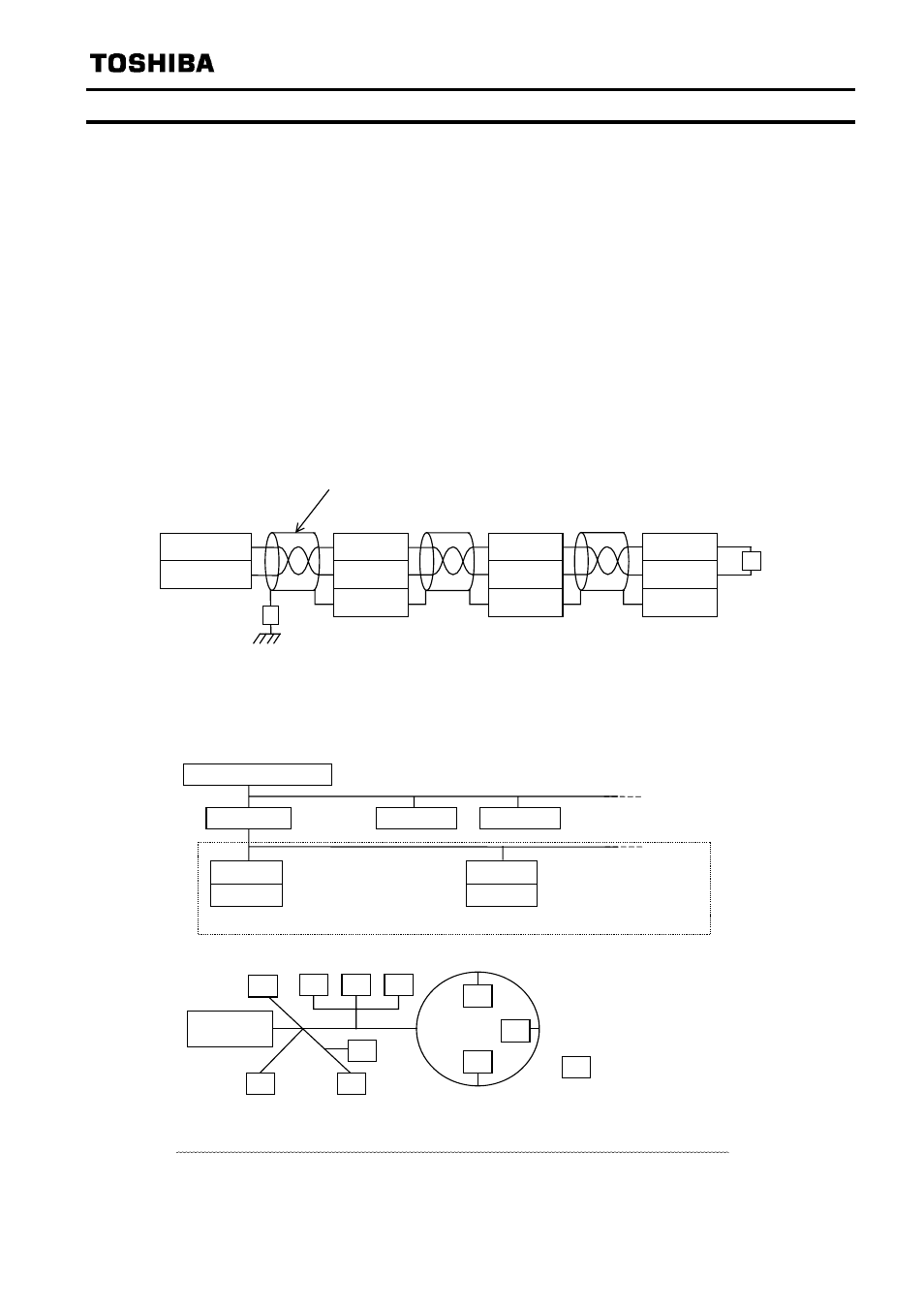
Make up the network as follows.
- Transmission/reception signals (NETA, NETB)
Make up the communication path by connecting all transmission/reception data cables (No polarity).
- Grounding the shield of cable (SHLD)
Connect the all shield lines of network cable. Ground through a metal film resistor of 470k ohm,
1/4W, 10% or more accurate so that static electricity does not increase (at the point where it
separated from the power ground of inverters or motors).
- Termination resistor (Please refer to “3.5. Termination resistor”)
Only one terminal resistor is needed for the segment of the free topology. It can also be placed
wherever it is on the free topology segments. (2 termination resistors in case of Bus topology)
- Network cable length (for recommended cable usage)
Free-Topology: device-to-device distance is 400m or less, total wire length is 500m or less
Bus-Topology: total wire length is 1400m or less, stub length is 3m or less.
Twisted pair cable with shield
Host computer
/ Router
LIU007Z
Terminal resistor
52.3ohm, 1/8W
Shield grounding
resistor
NETA
NETB
SHLD
LIU007Z
NETA
NETB
SHLD
LIU007Z
NETA
NETB
SHLD
Terminal 1
Terminal 2
- Connection image
Network configuration is shown in the figures below. This L
ON
W
ORKS
communication option has
TP/FT-10 channel type transceiver. The free topology wiring supported by the TP/FT-10 channel
type accommodates bus, star, loop, or several combinations of these topologies shown in below
Number of connected units to the router: 63 nodes at maximum
LIU007Z
VF-FS1
Free topology: 63 units connected at maximum
Host computer
Router
LIU007Z
- The free topology wiring example.
means a node
Termination
resistor
VF-FS1
- Network configuration example
Complex topology can be configured
Router
Router
N.B.: Do not connect the SHLD terminal to the power ground of inverters or other units.
Keep the network cables 20cm or more separate from the power cables to prevent from
malfunctioning due to electromagnetic noise.