Operating pressures – Trane WPWD User Manual
Page 23
WSHP-SVX02A-EN
23
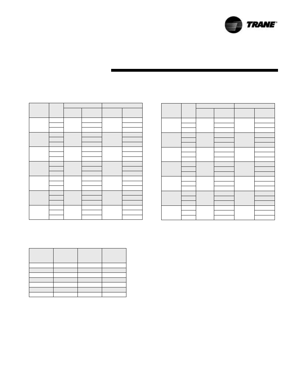
Operating Pressures
Table 7: Heating water pressure drops (WPD) in feet of head
Unit Size
GPM
Source
Load
EWT
F
Ft. Head
Pressure
EWT
F
Ft. Head
Pressure
024
3.8
60
1.5
80
1.3
7.0
5.1
4.5
8.9
8.3
7.2
036
4.6
60
2.2
80
1.9
8.5
7.6
6.6
10.8
12.2
10.6
042
5.2
60
2.8
80
2.4
9.5
9.8
8.6
12.1
16.2
14.1
048
6.0
60
3.8
80
3.3
11.0
13.3
11.6
14.0
21.9
19.1
060
7.6
60
6.2
80
5.4
14.0
21.9
19.1
17.8
36.1
31.5
072
8.7
60
8.2
80
7.1
16.0
28.9
25.3
20.4
47.9
41.8
240
30.0
60
3.4
80
2.9
55.0
9.2
8.1
70.0
13.9
12.2
Note: The EXWA 240 has two circuits.
Water Pressure Drop
Tables 6 and 7 should be used to define feet of head/pressure drop. Note: To calculate feet of head, when using gauges that read in PSIG,
multiply PSI by 2.31.
Flow Checks
For the operating temperature drop (heating) and rise (cooling), refer to Table OP1 and OP2 for the proper water tempera-
ture change. Depending on the unit size, entering water temperature and water flow rate, the cooling temperature rise is
from 8°F-16°F. Based on the same criteria for heating, the temperature drop is from 2°F-13°F.
Pressure
Using the P/T ports and one 0-60 psi pressure gauge with the P/T port adapter, measure the pressure difference between
the water-in and water-out connections. Compare the pressure differential to Table 6 to determine flow.
Start-up Checklist and Log
Use the form on page 24 to log system and unit temperatures during start-up.
Table 6: Cooling water pressure drops (WPD) in feet of head
Unit Size
GPM
Source
Load
EWT
F
Ft. Head
Pressure
EWT
F
Ft. Head
Pressure
024
3.8
80
1.3
53.6
1.6
7.0
4.5
5.4
8.9
7.2
8.7
036
4.6
80
1.9
53.6
2.3
8.5
6.6
7.9
10.8
10.6
12.7
042
5.2
80
2.4
53.6
3.0
9.5
8.6
10.3
12.1
14.1
17.1
048
6.0
80
3.3
53.6
4.0
11.0
11.6
14.0
14.0
19.1
23.1
060
7.6
80
5.4
53.6
6.5
14.0
19.1
23.1
17.8
31.5
38.1
072
8.7
80
7.1
53.6
8.6
16.0
25.3
30.5
20.4
41.8
50.5
240
30.0
80
2.9
53.6
3.6
55.0
8.1
9.7
70.0
12.2
14.7
Water Volume
Table 8 is provided for use in calculating glycol requirements for the unit.
Table 8: Water volume
Unit Size
Water Side
Volume
Cubic In.
Water Side
Volume
Cubic Ft.
Water Side
Volume
Gallons
024
55
0.032
0.238
036
105
0.061
0.455
042
105
0.061
0.455
048
259
0.150
1.121
060
259
0.150
1.121
072
259
0.150
1.121
240
1057
0.615
4.576