Characteristics, functions, and applications – TDK J Series JBW User Manual
Page 17
(17/30)
004-02 / 20070523 / ea122_jbw.fm
• All specifications are subject to change without notice.
Characteristics, Functions, and Applications
10 to 50W TYPES
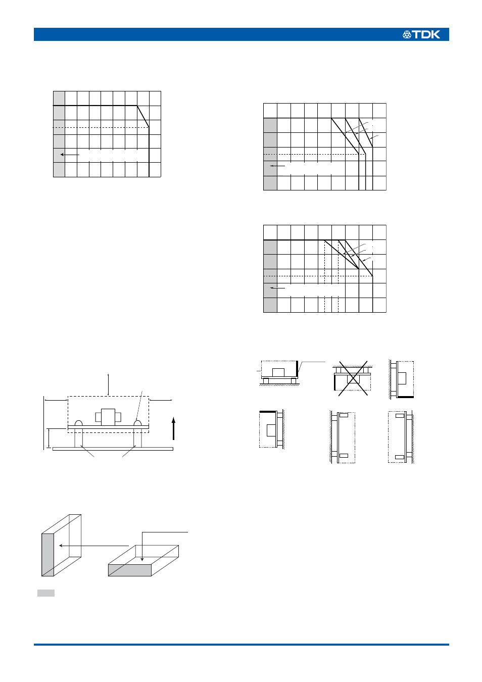
OUTPUT POWER-AMBIENT TEMPERATURE(DERATINGS)
INSTALLATIONS
• Mounting the power supply at the four corners with metal spac-
ers (2 corners for 10W models).
• Maintain a min. 4mm clearance distance in order to satisfy insu-
lation and high voltage safety requirements.
• Lay an insulating sheet under the power supply in case a min.
8mm installation space cannot be secured between the PC
board and the housing.
• Provide a min. 4mm distance between heat sink or component
surface and surrounding objects in order to cause a thermal con-
vection.
• Since components are mounted on the back (solder) side of the
product, sufficient care should be taken when handling the
power supply to protect the PC board from shock, vibration, tor-
sion, etc. which can result in damage caused by cracked chip
components.
To install the power supply in a device, apply the standard installa-
tion direction (A) or (B).
In case of an installation in other directions, please contact TDK.
75 to 150W TYPES
OUTPUT POWER-AMBIENT TEMPERATURE(DERATINGS)
75, 100W TYPES
150W TYPE
INSTALLATION DIRECTION
There are installation directions (B) to (F) as shown below in addi-
tion to the standard installation direction (A) for mounting the
power supply on an apparatus. The installation (B), however, is
inhibited because it will cause heat to be trapped inside the power
supply.
Derating of the output voltage and the ambient temperature for the
installation directions (C) to (F) are not the same as for the direc-
tion (A). Please consult us if you need.
20
40
60
80
100
–20 –10
0
10
20
30
40
50
60
71
70
Ambient temperature(˚C)
Output power(%)
Available operating range
(outside of warranty)
;
8mm
min.
4mm
min.
4mm
min.
Metal spacer
ø6mm max.
4mm
min.
Power
supply
Mounting screw dia.: 3mm
Housing
UP
+
+
;
;
(A)
(B)
Component surface
Component surface
The shaded portion indicates a side in which an output
connector is arranged.
(A)
(C),(D)
(E),(F)
20
0
40
60
80
100
0
10
20
30
40
50
60
Ambient temperature(˚C)
Output power(%)
Available operating range
(outside of warranty)
–20 –10
(C),(D)
(E),(F)
(A)
20
0
40
60
80
100
0
10
20
30
40
50
60
50
Ambient temperature(˚C)
Output power(%)
Available operating range
(outside of warranty)
–20 –10
(B)
(C)
(D)
(E)
(F)
IN
OUT
IN
OUT
Heat sink
(A) Standard installation
Components