Jbw150w type – TDK J Series JBW User Manual
Page 15
(15/30)
004-02 / 20070523 / ea122_jbw.fm
• All specifications are subject to change without notice.
JBW150W Type
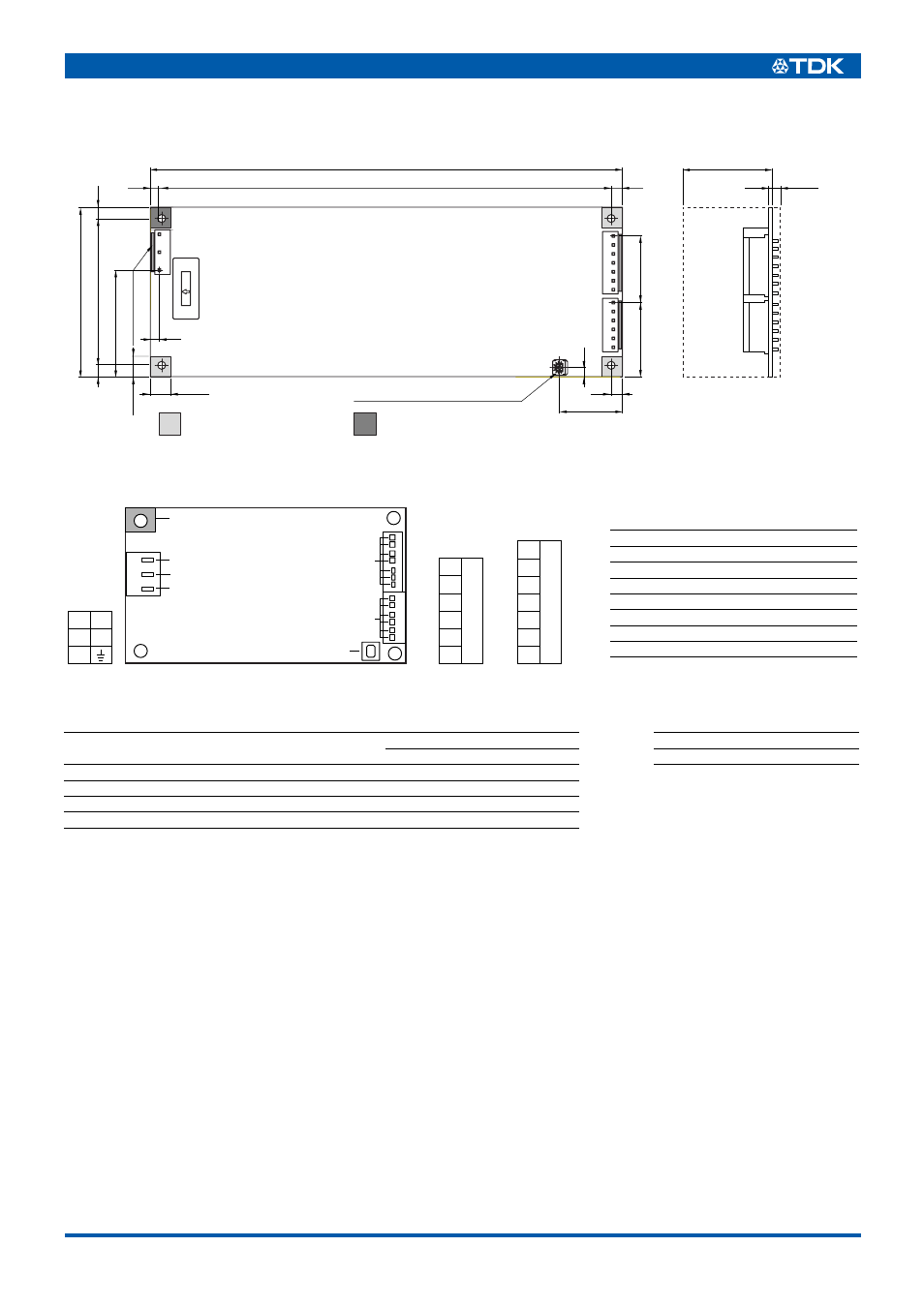
SHAPES AND DIMENSIONS
TERMINAL DESIGNATION
Connector made by
Power supply side
connector
Cable Side
Option
Part No.
Housing
Terminal
Set
4EU00G062
Japan Solderless Terminal Co., Ltd.
Input Connector(CP1)VH Series
B3P5-VH-B
VHR-5N
SVH-21T-P1.1
Output Connector(CP2)VH Series
B6P-VH-B
VHR-6N
SVH-21T-P1.1
Output Connector(CP3)VH Series
B7P-VH-B
VHR-7N
SVH-21T-P1.1
UP
( 5
)
9max.
1
7
1
6
CP2
CP3
5
3
1
CP1
Area for spacer(ø
6max.)
Solder Side
(
3 Places)
Ground pattern area(ø
6max.)
Solder Side
(
1 Place)
222
5.0
212±0.5
37
9max.
(4)
(4)
(5)
(27.9)
75
65±0.5
5
( 47.2
)
( 32.7
)(
29.5
)
Input
connector
Output voltage adjustment trimmer
( 4
)
3max.
1.6
Dimensions in mm
±1mm : without specified dimensions
· Japan Solderless Terminal Co., Ltd.
VH Series B7P-VH-B
· Japan Solderless Terminal Co., Ltd.
VH Series B3P5-VH-B
· Japan Solderless Terminal Co., Ltd.
VH Series B6P-VH-B
2
3
1
3
5
1
4
7
5
6
P1
CP1
CP1
P3
N
L
P5
CP3
P1
P2
P3
P4
P5
P6
P7
–
CP3
CP2
CP2
P1
P2
P3
P4
P5
P6
+
1
7
1
6
Terminal No.
Designations
1
Input terminal(L)
2
Input terminal(N)
3
Frame ground terminal(G)
4
Ground pad
5
–Output terminal(–)
6
+Output terminal(+)
7
Output voltage setting trim(+)