Toshiba VF-nC1 User Manual
Page 85
E6581090
F-21
6
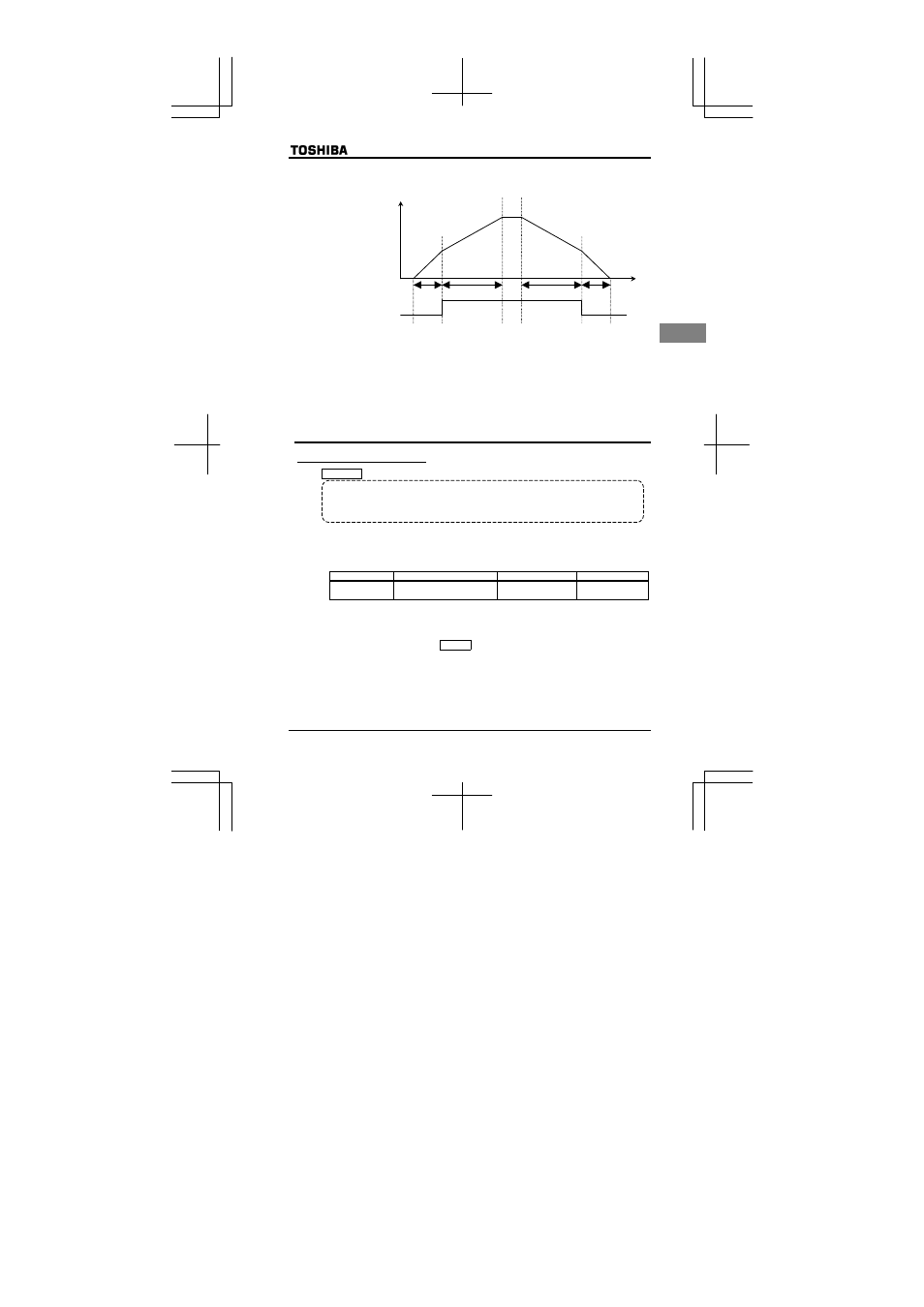
2) Changing the acceleration/deceleration time by adjusting the contact input signal
– Changing the acceleration/deceleration time, using external terminals –
③
Decelerated at the gradient
of time set with H
④
Decelerated at the gradient
of time set with FGE
①
Accelerated at the gradient of
time set with CEE
②
Accelerated at the gradient of
time set with H
Output frequency [Hz]
④
①
②
③
R(AD2)-CC
Time (sec)
0
ON
OFF
☆
This switching is done when acceleration/deceleration 2 (AD2) is assigned to the R terminal (when
H
(input terminal selection 2) is set to 5 (acceleration/deceleration 2)), using the multi-
function programmable input terminal function.
In this case, set EOQF to 0 (terminal block).
No signal for switching to acceleration/deceleration 2 is set by default. If necessary, assign
function 5 (AD2) to an unassigned terminal, using the input terminal selection function.
6.14
Protection functions
6.14.1 Current stall setting
H : Stall prevention level
• Function
If a current exceeding the level specified with H, the stall prevention function is activated
to decrease the output frequency.
When specifying a value larger than 100 (%), set also the VMT parameter (motor electronic
thermal protection level) properly.
■
Parameter setting
Title
Function
Adjustment range
Default setting
H
Stall prevention level
30~199 (%)
200: Invalid
150
[Message displayed along with an QE alarm]
If an QE alarm goes off (if a current exceeding the stall prevention level), the output frequency
displayed will change and the “E” on the left of it will blink.
Example of display :
E