Toshiba VF-nC1 User Manual
Page 54
E6581090
E-2
5
☆
The following control input terminals are always operative, no matter how the EOQF parameter
(command mode selection) and the HOQF parameter (frequency setting mode selection) are
set.
• Reset terminal (enabled only when a trip occurs.)
• Standby terminal
• External input trip stop terminal
☆
Before changing the setting of the EOQF parameter (command mode selection) or the HOQF
parameter (frequency setting mode selection), be sure to put the inverter out of operation. (When
H
is set to , the settings of these parameters can be changed even during operation.)
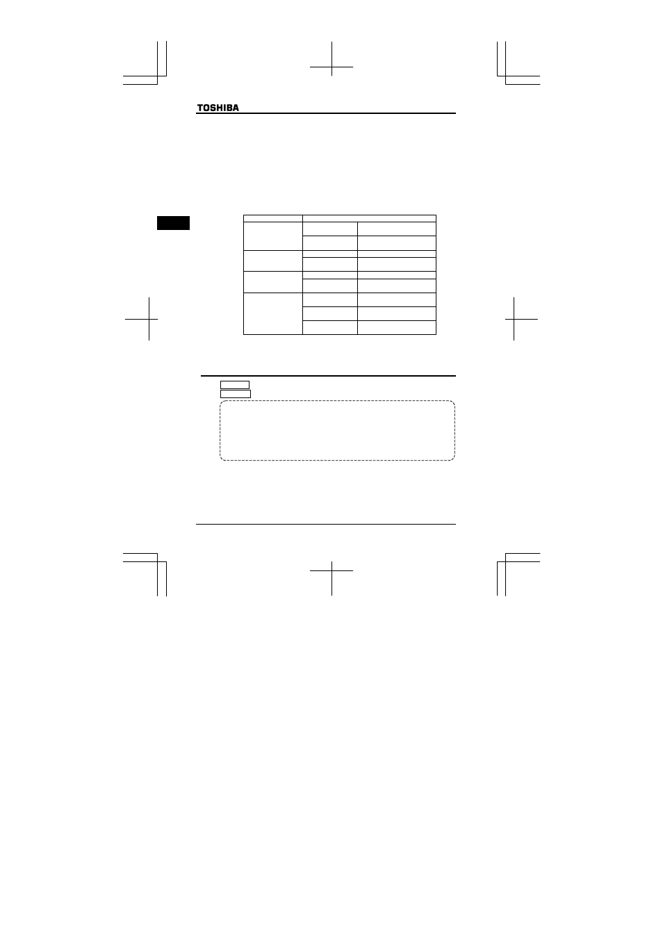
• There are two kinds of functions: function of responding to signals from the device specified with
the HOQF parameter and function of responding to signals from the terminal board only.
• When the highest-priority command is entered from an external device or a terminal board, it
takes priority over commands from the device specified with the HOQF parameter.
HOQF
=0
VI input
PNL/TB:OFF
UP and DOWN keys on
operation panel
HOQF
=1
PNL/TB:ON
VI input
EOQF
: Terminal board
PNL/TB:OFF
Internal potentiometer
HOQF
=2
PNL/TB:ON
VI input
EOQF
: Terminal board
PNL/TB:OFF
Serial communications
HOQF
=3
PNL/TB:ON
VI input
EOQF
: Terminal board
FCHG:OFF
PNL/TB:OFF
Internal potentiometer
FCHG:ON
PNL/TB:OFF
VI input
HOQF
=4
PNL/TB:ON
VI input
EOQF
: Terminal board
5.2
Meter setting and adjustment
HOUN : FM/OUT terminal functions selection
HO : Meter adjustment
• Function
The FM/OUT terminal can be switched between meter output (PWM output) and open
collector. When connecting a meter to the FM/OUT terminal, set the HOUN parameter to a
number other than -1 (open collector output) and connect the meter between FM/OUT
(positive side) and CC (negative side).
If you want to connect a meter to the inverter, choose a full-scale 0~1mAdc ammeter or a
full-scale 0~7.5Vdc-1mA voltmeter.
The meter output of VFNC1 may have some errors because of PWM waveform.
Especially if the meter output is near 0, the errors may be increased.
* To switch between current input and voltage input, use the H parameter
(Analog input / logic input function selection).