Solid state starter, Jksss7+ series – Toshiba XT JK Series User Manual
Page 4
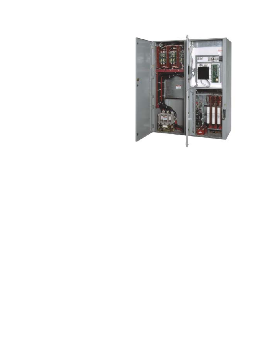
The new JKSSS7+ Series of motor starter is the
result of extensive research and development.
These medium voltage solid state starters are
available for the control of induction, wound rotor
or synchronous motors up to 4.8kV. All control-
lers are designed to meet NEMA Class E2
requirements.
Features
Isolated Low Voltage Compartment
SOLID STATE STARTER
JKSSS7+ Series
Options
Soft Start
125% Continuous Duty
500% - 60 Seconds, 600% - 30 Seconds
Digital Microprocessor Control
LCD Display w/Programming Keypad
Toshiba Medium Voltage Vacuum Contactors,
for Bypass and Input Isolation
Incoming, 720A JK Disconnect Switch - Bolted
Pressure Switch Connections
Current Limiting, High Interrupting Capacity,
"R" Rated Motor Starting Fuses
Two Stage Solid State Motor Protection -
Starting: Programmable for Class 5 through 30
Running: Programmable for Class 5 through 30
Control Power Transformers with Primary and
Secondary Fuses
NEMA Type 1 Enclosure
Separate Medium and Low Voltage Compartments
Mechanical and Electrical Interlocks
NEMA Type 12 or 3R Enclosure
1200 or 2000A Main Copper Bus
Available in MCC Lineups with Other JK Series
Starters (FVNR, FVR, RVAT, Synchronous, Etc.)
Available in MCC Lineups with Main Incoming
Disconnect Switch or Vacuum Circuit Breaker
The soft start is available as a controller only for
users which already have an existing full voltage
starter (disconnect switch, main power fuses &
contactor) and wants reduced voltage starting
and soft stop features.
PFC Contactor - Vacuum contactor for switching
Power Factor Correction Capacitor.
Manual (Full Voltage) Bypass Selection with solid
state protection (2E) or bimetallic overload.
The low voltage section is oversized and is at a
convenient height. This section is isolated from
the medium voltage section.
Digital Control Module
LCD Display (two lines) and Status LEDs
(Power, Run, Alarm, Aux. Relays)
Programming Keypad (Non-volatile Memory)
Visible, Bolted Pressure, Isolation Switch
Less Resistance
Less Wear
Zero Insertion Pressure
Mechanical Interlocking System
Maintenance Data
Fault indications: Shorted SCR, Phase Loss, Shunt
Trip, Phase Imbalance, Phase Rotation, Overload,
Overtemp, Overcurrent, Short Circuit, Load Loss,
Ground Fault, Tach Accel Trip, Stator Phase Trip,
RTD Trip, or Any Trip
Coast Down Time
Starts per Hour
Time Between Starts
Any Lockout
Event History - Up to 60 events. Data includes
cause, date, time, phase and ground current.
Adjustments
Motor Full Load Ampere (FLA)
Dual Adjustments - Two independent settings
Initial Voltage 0 - 100% of nominal voltage
Current Limit 200 - 500% of motor FLA
Acceleration Time 1 - 120 seconds
Deceleration Time 1 - 60 seconds
Three custom Accel curves
Jog: 5 - 100% Volt., 1 - 20 sec., Current 100 - 500%
Kick Start: 10 - 100% Voltage, 0.1 - 2 sec.
Coast Down (Back Spin) Lockout Timer 1 - 60 min.
Starts-per-Hour Lockout Timer
1 - 10 successful starts per hour
1 - 60 min. between start attempts
Undercurrent 10 - 90% (w/1 - 60 sec trip delay)
Overload Reset - Selectable Manual or Automatic
Two 4 - 20 mA Analog Outputs: Selectable from
Off, RPM, Hottest Non-Stator RTD, Hottest Stator
RTD, RMS Current, % of Motor Load