Taylor SLUSH 382 User Manual
Page 7
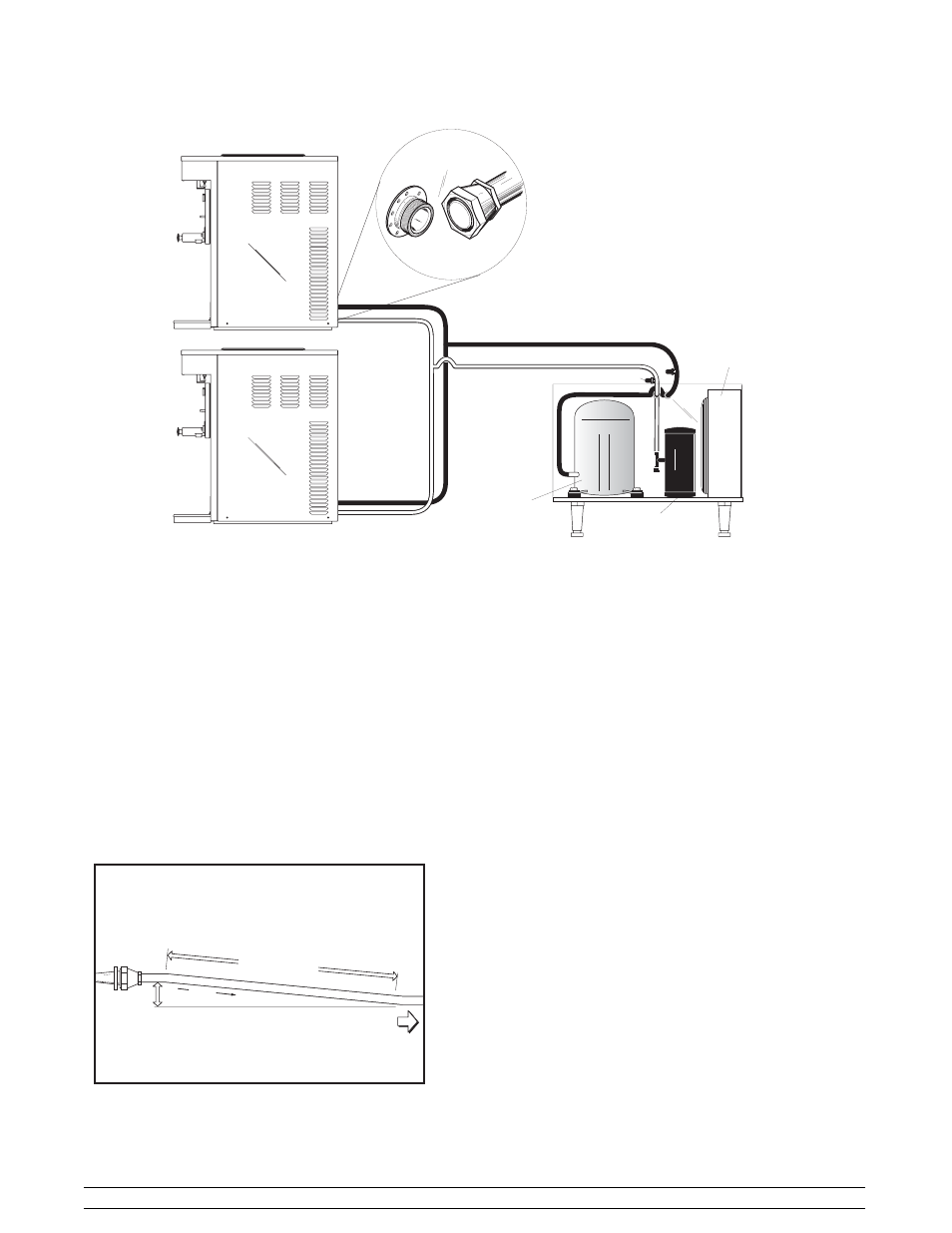
3
Models 382/RC25
To the Installer
Note: 5/8” individual line lengths are not to exceed 75 ft. (22.8 m) maximum length each.
Total line length is not to exceed 150 ft. (45.7 m). 5/8” line + 5/8” line + 3/4” line = 150 ft. or less.
Figure 2
Compressor
Condenser
Liquid Refrigerant
Reciever
CONDENSING UNIT
Access Valve
DISPENSER UNIT
382
DISPENSER UNIT
382
Installation
Step 1
Install refrigeration lines from the dispenser to the
condensing unit. Do not create oil traps.
Note: For proper oil return, installation of horizontal
suction lines are to be sloped downward in the
direction of the condensing unit. The slope must be a
minimum 1/4” (6.4 mm) angle per 10 ft. (30.48 mm) of
line length.
FROM
DISPENSER
TO CONDENSER
¼" (.64 cm)
FLOW
10'-0"
(3.048 m)
Figure 3
Normally, any straight run of tubing must be supported
near each end of the run. Long runs require additional
supports. As a guide, 3/8” to 3/4” copper should be
supported every 5 ft. (1.5 m). When changing
directions, no corner should be left unsupported.
Supports should be placed a maximum of 2 ft. (.61 m)
in each direction from the corner. If soft copper tube is
used, make sure it is not kinked or flattened. If hard
drawn copper tubing is used, use only long radius
elbows.
Step 2
Braze the supplied quick connect/disconnect
couplings on the dispenser end of the refrigeration
lines. Couplings are supplied with the dispenser.
Step 3
Braze the quick connect/disconnect couplings and
access tees on the condensing unit end of the
refrigeration lines. Couplings and access tees are
supplied with the unit.
Note: Wrap a wet cloth around the brass coupling
bodies to prevent heat damage to the seal.
Step 4
Test the field constructed lines for leaks.