Asus P4-P5N9300 User Manual
Page 40
3-8
Chapter 3: Motherboard info
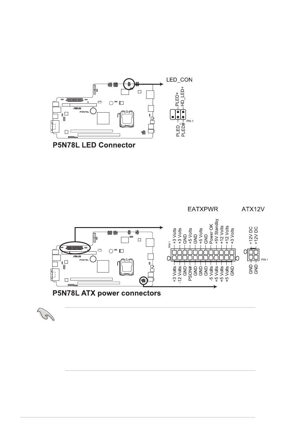
5. LED connector (6-1 pin LED_CON)
This connector supports the Power and HDD activity LEDs in the system front
panel.
6. ATX power connectors (24-pin EATXPWR, 4-pin ATX12V)
These connectors are for ATX power supply plugs. The plugs from the power
supply are designed to fit these connectors in only one orientation. Find the
proper orientation and push down firmly until the connectors completely fit.
• DO NOT forget to connect the 4-pin ATX +12 V power plug; otherwise, the
system will not boot.
• We recommend that you use a PSU with a higher power output when
configuring a system with more power-consuming devices. The system
may become unstable or may not boot up if the power is inadequate.
• Ensure that your power supply unit (PSU) can provide at least the minimum
power required by your system.
- CG8565 (410 pages)
- CG8565 (246 pages)
- CS5120 (1 page)
- CS5111 (26 pages)
- ET1611PUK (38 pages)
- S2-P8H61E (80 pages)
- P2-P5945GCX (90 pages)
- P2-PH1 (80 pages)
- P1-P5945G (80 pages)
- CG8270 (534 pages)
- CG8270 (362 pages)
- CG8270 (218 pages)
- CG8270 (536 pages)
- CG8270 (72 pages)
- CG8270 (76 pages)
- P3-P5G31 (100 pages)
- P3-PH4 (80 pages)
- P2-M2A690G (8 pages)
- P2-M2A690G (80 pages)
- P4-P5N9300 (1 page)
- P2-P5945GC (92 pages)
- P1-P5945GC (92 pages)
- P3-P5G33 (98 pages)
- T3-P5945GC (80 pages)
- T3-P5945GCX (80 pages)
- P2-M2A690G (94 pages)
- T3-PH1 (82 pages)
- T3-PH1 (80 pages)
- T5-P5G41E (76 pages)
- T5-P5G41E (82 pages)
- S1-AT5NM10E (68 pages)
- P6-P7H55E (67 pages)
- ES5000 (174 pages)
- T4-P5G43 (104 pages)
- T-P5G31 (92 pages)
- BT6130 (60 pages)
- BT6130 (54 pages)
- BT6130 (2 pages)
- CG8265 (350 pages)
- CG8265 (210 pages)
- CM1740 (330 pages)
- CM1740 (70 pages)
- CM1740 (198 pages)
- P6-M4A3000E (59 pages)